

Hydromechanics 7.1 Dimensional Analysis, Basic Estimation, and Model Testing 151
Part A | 7.1
a)
b)
Fig. 7.36 (a) Surface piercing hydrofoil; (b) fully submerged hydrofoils (after [7.33])
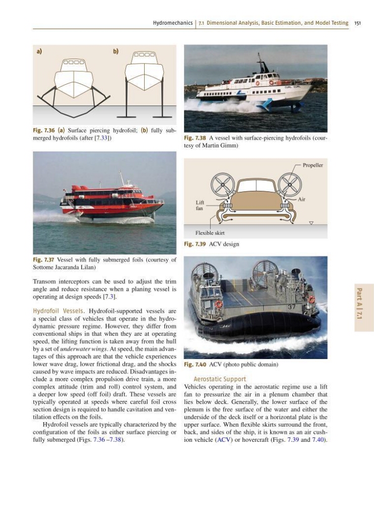
Fig. 7.37 Vessel with fully submerged foils (courtesy of
Sottome Jacaranda Lilan)
Transom interceptors can be used to adjust the trim
angle and reduce resistance when a planing vessel is
operating at design speeds [7.3].
Hydrofoil Vessels. Hydrofoil-supported vessels are
a special class of vehicles that operate in the hydrodynamic pressure regime. However, they differ from
conventional ships in that when they are at operating
speed, the lifting function is taken away from the hull
by a set of underwater wings. At speed, the main advantages of this approach are that the vehicle experiences
lower wave drag, lower frictional drag, and the shocks
caused by wave impacts are reduced. Disadvantages include a more complex propulsion drive train, a more
complex attitude (trim and roll) control system, and
a deeper low speed (off foil) draft. These vessels are
typically operated at speeds where careful foil cross
section design is required to handle cavitation and ventilation effects on the foils.
Hydrofoil vessels are typically characterized by the
configuration of the foils as either surface piercing or
fully submerged (Figs. 7.36 –7.38).
Fig. 7.38 A vessel with surface-piercing hydrofoils (courtesy of Martin Gimm)
Air
Lift
fan
Flexible skirt
Propeller
Fig. 7.39 ACV design
Fig. 7.40 ACV (photo public domain)
Aerostatic Support
Vehicles operating in the aerostatic regime use a lift
fan to pressurize the air in a plenum chamber that
lies below deck. Generally, the lower surface of the
plenum is the free surface of the water and either the
underside of the deck itself or a horizontal plate is the
upper surface. When flexible skirts surround the front,
back, and sides of the ship, it is known as an air cushion vehicle (ACV) or hovercraft (Figs. 7.39 and 7.40).
Part A | 7.1
a)
b)
Fig. 7.36 (a) Surface piercing hydrofoil; (b) fully submerged hydrofoils (after [7.33])
Fig. 7.37 Vessel with fully submerged foils (courtesy of
Sottome Jacaranda Lilan)
Transom interceptors can be used to adjust the trim
angle and reduce resistance when a planing vessel is
operating at design speeds [7.3].
Hydrofoil Vessels. Hydrofoil-supported vessels are
a special class of vehicles that operate in the hydrodynamic pressure regime. However, they differ from
conventional ships in that when they are at operating
speed, the lifting function is taken away from the hull
by a set of underwater wings. At speed, the main advantages of this approach are that the vehicle experiences
lower wave drag, lower frictional drag, and the shocks
caused by wave impacts are reduced. Disadvantages include a more complex propulsion drive train, a more
complex attitude (trim and roll) control system, and
a deeper low speed (off foil) draft. These vessels are
typically operated at speeds where careful foil cross
section design is required to handle cavitation and ventilation effects on the foils.
Hydrofoil vessels are typically characterized by the
configuration of the foils as either surface piercing or
fully submerged (Figs. 7.36 –7.38).
Fig. 7.38 A vessel with surface-piercing hydrofoils (courtesy of Martin Gimm)
Air
Lift
fan
Flexible skirt
Propeller
Fig. 7.39 ACV design
Fig. 7.40 ACV (photo public domain)
Aerostatic Support
Vehicles operating in the aerostatic regime use a lift
fan to pressurize the air in a plenum chamber that
lies below deck. Generally, the lower surface of the
plenum is the free surface of the water and either the
underside of the deck itself or a horizontal plate is the
upper surface. When flexible skirts surround the front,
back, and sides of the ship, it is known as an air cushion vehicle (ACV) or hovercraft (Figs. 7.39 and 7.40).