

Part A | 7.1
150 Part A Fundamentals
HYSWAS
SWATH
Semi-SWATH
AFT
FWD
Fig. 7.32 SWATH concept –
HYSWAS (hydrofoil SWA ship);
SWATH (SWA twin hull) (after [7.32])
a)
b)
Fig. 7.33 (a) SWATH hull form
(courtesy of Yacht Silver Cloud);
(b) Catamaran hull form (viewed from
stern)
it is ventilated and exposed to the atmosphere. With
this geometry, positive dynamic pressure forces are
generated in the flow at the stern, which reduce the
squatting and large pitch angles seen in displacement vessels at higher Froude numbers.
3. Planing hulls:
1:0 1:2 Ä Fr mainly hydrodynamically generated
forces carry the weight of the vessel. At speed, the
boat starts to ride up and over the crest of its own
bow wave. A lower fraction of the hull is submerged
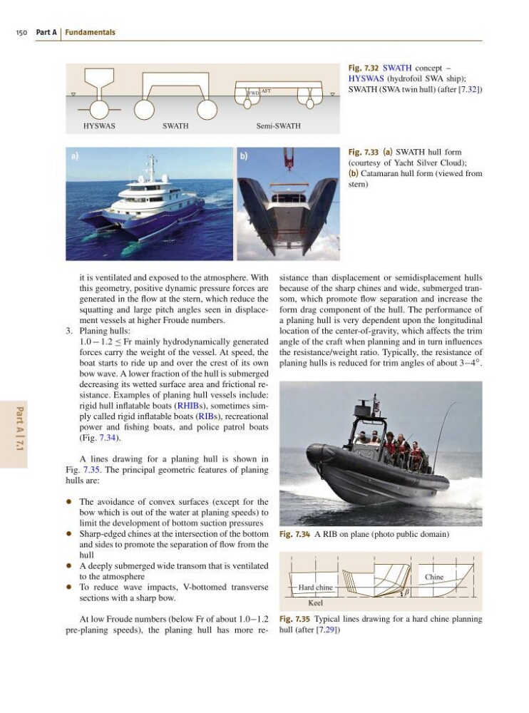
decreasing its wetted surface area and frictional resistance. Examples of planing hull vessels include:
rigid hull inflatable boats (RHIBs), sometimes simply called rigid inflatable boats (RIBs), recreational
power and fishing boats, and police patrol boats
(Fig. 7.34).
A lines drawing for a planing hull is shown in
Fig. 7.35. The principal geometric features of planing
hulls are:
The avoidance of convex surfaces (except for the
bow which is out of the water at planing speeds) to
limit the development of bottom suction pressures
Sharp-edged chines at the intersection of the bottom
and sides to promote the separation of flow from the
hull
A deeply submerged wide transom that is ventilated
to the atmosphere
To reduce wave impacts, V-bottomed transverse
sections with a sharp bow.
At low Froude numbers (below Fr of about 1:01:2
pre-planing speeds), the planing hull has more resistance than displacement or semidisplacement hulls
because of the sharp chines and wide, submerged transom, which promote flow separation and increase the
form drag component of the hull. The performance of
a planing hull is very dependent upon the longitudinal
location of the center-of-gravity, which affects the trim
angle of the craft when planning and in turn influences
the resistance/weight ratio. Typically, the resistance of
planing hulls is reduced for trim angles of about 34
ı .
Fig. 7.34 A RIB on plane (photo public domain)
β
Chine
Hard chine
Keel
Fig. 7.35 Typical lines drawing for a hard chine planning
hull (after [7.29])
150 Part A Fundamentals
HYSWAS
SWATH
Semi-SWATH
AFT
FWD
Fig. 7.32 SWATH concept –
HYSWAS (hydrofoil SWA ship);
SWATH (SWA twin hull) (after [7.32])
a)
b)
Fig. 7.33 (a) SWATH hull form
(courtesy of Yacht Silver Cloud);
(b) Catamaran hull form (viewed from
stern)
it is ventilated and exposed to the atmosphere. With
this geometry, positive dynamic pressure forces are
generated in the flow at the stern, which reduce the
squatting and large pitch angles seen in displacement vessels at higher Froude numbers.
3. Planing hulls:
1:0 1:2 Ä Fr mainly hydrodynamically generated
forces carry the weight of the vessel. At speed, the
boat starts to ride up and over the crest of its own
bow wave. A lower fraction of the hull is submerged
decreasing its wetted surface area and frictional resistance. Examples of planing hull vessels include:
rigid hull inflatable boats (RHIBs), sometimes simply called rigid inflatable boats (RIBs), recreational
power and fishing boats, and police patrol boats
(Fig. 7.34).
A lines drawing for a planing hull is shown in
Fig. 7.35. The principal geometric features of planing
hulls are:
The avoidance of convex surfaces (except for the
bow which is out of the water at planing speeds) to
limit the development of bottom suction pressures
Sharp-edged chines at the intersection of the bottom
and sides to promote the separation of flow from the
hull
A deeply submerged wide transom that is ventilated
to the atmosphere
To reduce wave impacts, V-bottomed transverse
sections with a sharp bow.
At low Froude numbers (below Fr of about 1:01:2
pre-planing speeds), the planing hull has more resistance than displacement or semidisplacement hulls
because of the sharp chines and wide, submerged transom, which promote flow separation and increase the
form drag component of the hull. The performance of
a planing hull is very dependent upon the longitudinal
location of the center-of-gravity, which affects the trim
angle of the craft when planning and in turn influences
the resistance/weight ratio. Typically, the resistance of
planing hulls is reduced for trim angles of about 34
ı .
Fig. 7.34 A RIB on plane (photo public domain)
β
Chine
Hard chine
Keel
Fig. 7.35 Typical lines drawing for a hard chine planning
hull (after [7.29])