

Hydromechanics 7.1 Dimensional Analysis, Basic Estimation, and Model Testing 147
Part A | 7.1
of the vessel (r), that is, W D gr (Archimedes’
principle).
(2) Hydrodynamic: A vehicle pushes water downward
as it moves across the water surface, imparting
a downward momentum on fluid near the free surface. The resulting reaction force on the hull supports the vessel.
(3) Aerostatic: The pressure generated by a lifting fan at
the top of a plenum chamber supports the vehicle’s
weight, even when it has no forward velocity.
(4) Aerodynamic: Some marine vehicles rely on the
aerodynamic lift created by their forward velocity
to support themselves near the free surface.
Hydrostatic and Hydrodynamic Regimes
The majority of marine vessels operate in either the hydrostatic or the hydrodynamic-pressure regime above.
Since the hull is that part of a ship that generally supports its weight, hull design is strongly driven by the
operational regime. Good hull design is critical for
efficient powering, stability, controllability, and maneuverability [7.29]. The Froude number can be used to
determine whether a vehicle operates in pressure regime
(1), (2) or in an intermediate zone between regimes (1)
and (2). Here, the waterline-length-based Froude number is defined as
Fr Á
U
p
gL WL
;
(7.45)
where U is vehicle speed, g is the acceleration of gravity
and L WL is a length-scale characteristic of the dimension
of the ship parallel to the direction of the freestream flow
(often taken as the design waterline LWL).
Calm Water Wave Drag and the Froude Number
Limit of Displacement Hulls. As a ship or other
marine vessel moves across the water’s surface, it generates a distinctive pattern of waves, which create one
component of the overall drag by radiating energy from
Transverse
wave crests
Transverse wave
Diverging wave crests
Diverging waves
From stern
From bow
19.5°
54.4°
a)
b)
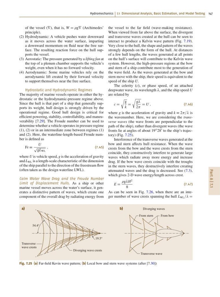
Fig. 7.25 (a) Far-field Kevin wave pattern; (b) Local bow and stern wave systems (after [7.30])
the vessel to the far field (wave-making resistance).
When viewed from far above the surface, the divergent
and transverse waves created at the hull can be seen to
interact to produce a Kelvin wave pattern (Fig. 7.19).
Very close to the hull, the shape and pattern of the waves
strongly depends on the form of the hull. At distances
of a few hull lengths, the waves generated at all points
on the hull’s surface will contribute to the Kelvin wave
system. However, the high-pressure regions at the bow
and stern of a ship contribute most to the generation of
the wave field. As the waves generated at the bow and
stern move with the ship, their speed is equivalent to the
speed of the ship U.
The celerity .c/, or phase speed, of an attached
deepwater wave, its wavelength , and the ship speed U
are related by
c D
r
g
k
D
r
g
2
D U ;
(7.46)
where g is the acceleration of gravity and k Á 2 is
the wavenumber. Here, we are considering the transverse waves (the wave fronts are perpendicular to the
path of the ship), rather than divergent waves (the wave
fronts lie at angles of about 19
ı 28
0 to the ship’s trajectory) (Fig. 7.25).
Interference of the transverse waves generated at the
bow and stern affects hull resistance. When the wave
crests from the bow and the wave crests from the stern
coincide, they constructively interfere to generate large
waves which radiate away more energy and increase
drag. If the bow wave crests coincide with the troughs
in the stern waves, they destructively interfere creating
attenuated waves and the drag is decreased. See (7.3),
which gives 2-D wave energy/length across crest.
E D
gH
2
8
(7.47)
As can be seen in Fig. 7.26, when there are an integer number of wave crests spanning the hull L WL == D
Part A | 7.1
of the vessel (r), that is, W D gr (Archimedes’
principle).
(2) Hydrodynamic: A vehicle pushes water downward
as it moves across the water surface, imparting
a downward momentum on fluid near the free surface. The resulting reaction force on the hull supports the vessel.
(3) Aerostatic: The pressure generated by a lifting fan at
the top of a plenum chamber supports the vehicle’s
weight, even when it has no forward velocity.
(4) Aerodynamic: Some marine vehicles rely on the
aerodynamic lift created by their forward velocity
to support themselves near the free surface.
Hydrostatic and Hydrodynamic Regimes
The majority of marine vessels operate in either the hydrostatic or the hydrodynamic-pressure regime above.
Since the hull is that part of a ship that generally supports its weight, hull design is strongly driven by the
operational regime. Good hull design is critical for
efficient powering, stability, controllability, and maneuverability [7.29]. The Froude number can be used to
determine whether a vehicle operates in pressure regime
(1), (2) or in an intermediate zone between regimes (1)
and (2). Here, the waterline-length-based Froude number is defined as
Fr Á
U
p
gL WL
;
(7.45)
where U is vehicle speed, g is the acceleration of gravity
and L WL is a length-scale characteristic of the dimension
of the ship parallel to the direction of the freestream flow
(often taken as the design waterline LWL).
Calm Water Wave Drag and the Froude Number
Limit of Displacement Hulls. As a ship or other
marine vessel moves across the water’s surface, it generates a distinctive pattern of waves, which create one
component of the overall drag by radiating energy from
Transverse
wave crests
Transverse wave
Diverging wave crests
Diverging waves
From stern
From bow
19.5°
54.4°
a)
b)
Fig. 7.25 (a) Far-field Kevin wave pattern; (b) Local bow and stern wave systems (after [7.30])
the vessel to the far field (wave-making resistance).
When viewed from far above the surface, the divergent
and transverse waves created at the hull can be seen to
interact to produce a Kelvin wave pattern (Fig. 7.19).
Very close to the hull, the shape and pattern of the waves
strongly depends on the form of the hull. At distances
of a few hull lengths, the waves generated at all points
on the hull’s surface will contribute to the Kelvin wave
system. However, the high-pressure regions at the bow
and stern of a ship contribute most to the generation of
the wave field. As the waves generated at the bow and
stern move with the ship, their speed is equivalent to the
speed of the ship U.
The celerity .c/, or phase speed, of an attached
deepwater wave, its wavelength , and the ship speed U
are related by
c D
r
g
k
D
r
g
2
D U ;
(7.46)
where g is the acceleration of gravity and k Á 2 is
the wavenumber. Here, we are considering the transverse waves (the wave fronts are perpendicular to the
path of the ship), rather than divergent waves (the wave
fronts lie at angles of about 19
ı 28
0 to the ship’s trajectory) (Fig. 7.25).
Interference of the transverse waves generated at the
bow and stern affects hull resistance. When the wave
crests from the bow and the wave crests from the stern
coincide, they constructively interfere to generate large
waves which radiate away more energy and increase
drag. If the bow wave crests coincide with the troughs
in the stern waves, they destructively interfere creating
attenuated waves and the drag is decreased. See (7.3),
which gives 2-D wave energy/length across crest.
E D
gH
2
8
(7.47)
As can be seen in Fig. 7.26, when there are an integer number of wave crests spanning the hull L WL == D