

Hydromechanics 7.1 Dimensional Analysis, Basic Estimation, and Model Testing 145
Part A | 7.1
Actuator Disk Model
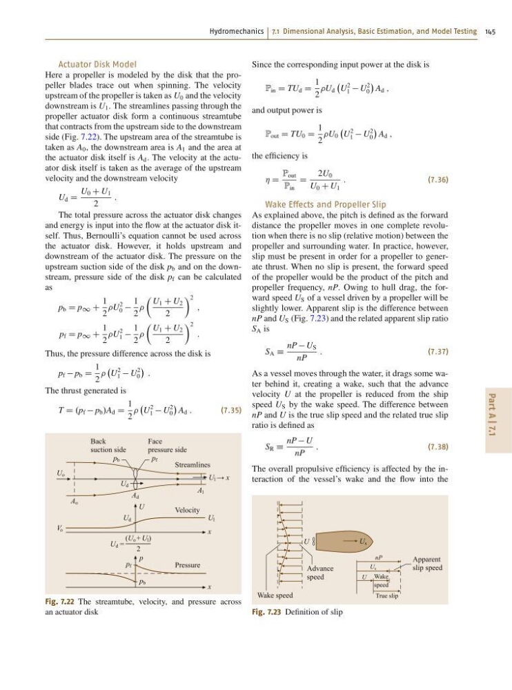
Here a propeller is modeled by the disk that the propeller blades trace out when spinning. The velocity
upstream of the propeller is taken as U 0 and the velocity
downstream is U 1 . The streamlines passing through the
propeller actuator disk form a continuous streamtube
that contracts from the upstream side to the downstream
side (Fig. 7.22). The upstream area of the streamtube is
taken as A 0 , the downstream area is A 1 and the area at
the actuator disk itself is A d . The velocity at the actuator disk itself is taken as the average of the upstream
velocity and the downstream velocity
U d D
U 0 C U 1
2
:
The total pressure across the actuator disk changes
and energy is input into the flow at the actuator disk itself. Thus, Bernoulli’s equation cannot be used across
the actuator disk. However, it holds upstream and
downstream of the actuator disk. The pressure on the
upstream suction side of the disk p b and on the downstream, pressure side of the disk p f can be calculated
as
p b D p 1 C
1
2
U
2
0
1
2
Â
U 1 C U 2
2
à 2
;
p f D p 1 C
1
2
U
2
1
1
2
Â
U 1 C U 2
2
à 2
:
Thus, the pressure difference across the disk is
p f p b D
1
2
U
2
1 U
2
0
:
The thrust generated is
T D .p f p b /A d D
1
2
U
2
1 U
2
0
A d :
(7.35)
Pressure
Back
suction side
Face
pressure side
p
U
x
Velocity
Streamlines
x
p b
p f
p b
p f
U d
U d
U l
U l → x
V o
A o
A l
A d
U o
U d =
(U o + U l )
2
Fig. 7.22 The streamtube, velocity, and pressure across
an actuator disk
Since the corresponding input power at the disk is
P in D TU d D
1
2
U d
U
2
1 U
2
0
A d ;
and output power is
P out D TU 0 D
1
2
U 0
U
2
1 U
2
0
A d ;
the efficiency is
Á D
P out
P in
D
2U 0
U 0 C U 1
:
(7.36)
Wake Effects and Propeller Slip
As explained above, the pitch is defined as the forward
distance the propeller moves in one complete revolution when there is no slip (relative motion) between the
propeller and surrounding water. In practice, however,
slip must be present in order for a propeller to generate thrust. When no slip is present, the forward speed
of the propeller would be the product of the pitch and
propeller frequency, nP. Owing to hull drag, the forward speed U S of a vessel driven by a propeller will be
slightly lower. Apparent slip is the difference between
nP and U S (Fig. 7.23) and the related apparent slip ratio
S A is
S A Á
nP U S
nP
:
(7.37)
As a vessel moves through the water, it drags some water behind it, creating a wake, such that the advance
velocity U at the propeller is reduced from the ship
speed U S by the wake speed. The difference between
nP and U is the true slip speed and the related true slip
ratio is defined as
S R Á
nP U
nP
:
(7.38)
The overall propulsive efficiency is affected by the interaction of the vessel’s wake and the flow into the
Apparent
slip speed
Advance
speed
Wake speed
Wake
speed
True slip
U s
U
U
U s
nP
Fig. 7.23 Definition of slip
Part A | 7.1
Actuator Disk Model
Here a propeller is modeled by the disk that the propeller blades trace out when spinning. The velocity
upstream of the propeller is taken as U 0 and the velocity
downstream is U 1 . The streamlines passing through the
propeller actuator disk form a continuous streamtube
that contracts from the upstream side to the downstream
side (Fig. 7.22). The upstream area of the streamtube is
taken as A 0 , the downstream area is A 1 and the area at
the actuator disk itself is A d . The velocity at the actuator disk itself is taken as the average of the upstream
velocity and the downstream velocity
U d D
U 0 C U 1
2
:
The total pressure across the actuator disk changes
and energy is input into the flow at the actuator disk itself. Thus, Bernoulli’s equation cannot be used across
the actuator disk. However, it holds upstream and
downstream of the actuator disk. The pressure on the
upstream suction side of the disk p b and on the downstream, pressure side of the disk p f can be calculated
as
p b D p 1 C
1
2
U
2
0
1
2
Â
U 1 C U 2
2
à 2
;
p f D p 1 C
1
2
U
2
1
1
2
Â
U 1 C U 2
2
à 2
:
Thus, the pressure difference across the disk is
p f p b D
1
2
U
2
1 U
2
0
:
The thrust generated is
T D .p f p b /A d D
1
2
U
2
1 U
2
0
A d :
(7.35)
Pressure
Back
suction side
Face
pressure side
p
U
x
Velocity
Streamlines
x
p b
p f
p b
p f
U d
U d
U l
U l → x
V o
A o
A l
A d
U o
U d =
(U o + U l )
2
Fig. 7.22 The streamtube, velocity, and pressure across
an actuator disk
Since the corresponding input power at the disk is
P in D TU d D
1
2
U d
U
2
1 U
2
0
A d ;
and output power is
P out D TU 0 D
1
2
U 0
U
2
1 U
2
0
A d ;
the efficiency is
Á D
P out
P in
D
2U 0
U 0 C U 1
:
(7.36)
Wake Effects and Propeller Slip
As explained above, the pitch is defined as the forward
distance the propeller moves in one complete revolution when there is no slip (relative motion) between the
propeller and surrounding water. In practice, however,
slip must be present in order for a propeller to generate thrust. When no slip is present, the forward speed
of the propeller would be the product of the pitch and
propeller frequency, nP. Owing to hull drag, the forward speed U S of a vessel driven by a propeller will be
slightly lower. Apparent slip is the difference between
nP and U S (Fig. 7.23) and the related apparent slip ratio
S A is
S A Á
nP U S
nP
:
(7.37)
As a vessel moves through the water, it drags some water behind it, creating a wake, such that the advance
velocity U at the propeller is reduced from the ship
speed U S by the wake speed. The difference between
nP and U is the true slip speed and the related true slip
ratio is defined as
S R Á
nP U
nP
:
(7.38)
The overall propulsive efficiency is affected by the interaction of the vessel’s wake and the flow into the
Apparent
slip speed
Advance
speed
Wake speed
Wake
speed
True slip
U s
U
U
U s
nP
Fig. 7.23 Definition of slip