

Hydromechanics 7.1 Dimensional Analysis, Basic Estimation, and Model Testing 143
Part A | 7.1
e) Using the slope of the lift curve in your equation of motion, determine the angle of attack ˛
required for the sail. Will it stall?
F L D
@C L
@˛
˛
1
2
air V
2
A l s s s
!
@C L
@˛
˛
1
2
air V
2
A l s s s sin ˇ D F H
Solving for ˛ gives
˛ D
F H
1
2
air V
2
A l s s s
@CL
@˛
sin ˇ
D 6:43
ı
:
From Fig. 7.16, we can see that this is smaller
than the stall angle, so the sail will not stall.
3. The keel: Here, the keel will be a thin flat plate with
a span of s k D 1:2 m and a chord of l k D 1:5 m. In
order to keep the lateral (transverse) component of
the aerodynamic forces F AS from pushing the yacht
off course, the keel must have a small leeway angle
(angle of attack) with respect to the boat’s course
(Fig. 7.17). Assuming F AS is balanced entirely by
the lift on the keel F HS , calculate .
From thin airfoil theory for a flat plate, the lift coefficient of the keel can be calculated as C Lk D 2
(where is in radians). Thus,
F HS D F AS D
1
2
sw V
2
S .2/s k l k :
Solving for and converting to degrees gives D
1:75
ı .
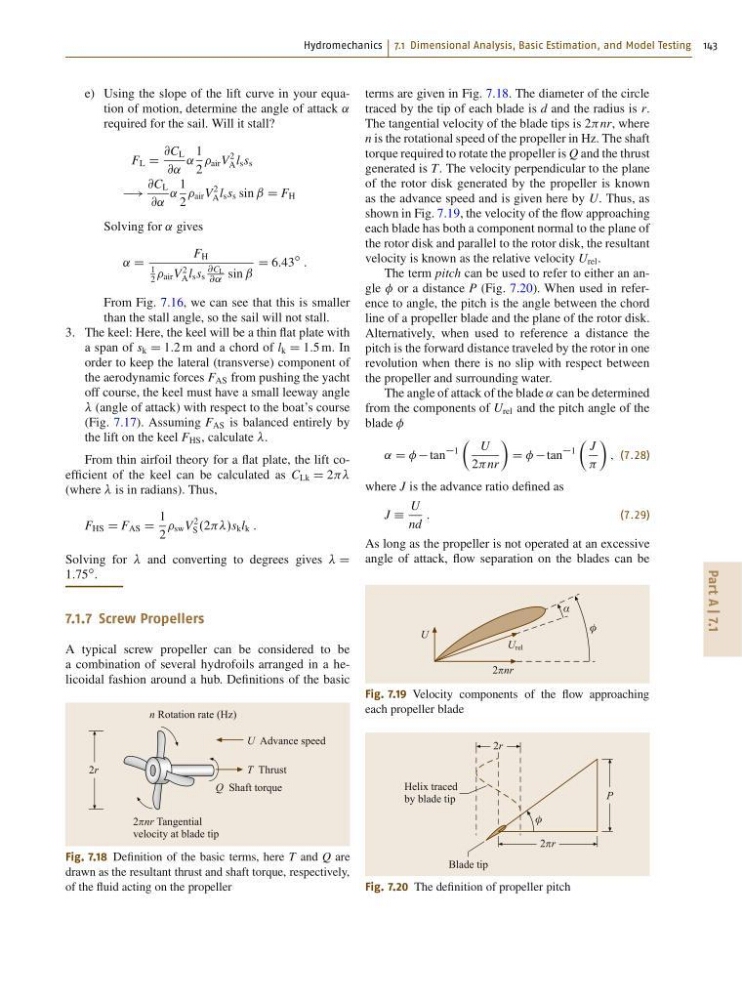
7.1.7 Screw Propellers
A typical screw propeller can be considered to be
a combination of several hydrofoils arranged in a helicoidal fashion around a hub. Definitions of the basic
n Rotation rate (Hz)
U Advance speed
T Thrust
Q Shaft torque
2nr Tangential
velocity at blade tip
2r
Fig. 7.18 Definition of the basic terms, here T and Q are
drawn as the resultant thrust and shaft torque, respectively,
of the fluid acting on the propeller
terms are given in Fig. 7.18. The diameter of the circle
traced by the tip of each blade is d and the radius is r.
The tangential velocity of the blade tips is 2nr, where
n is the rotational speed of the propeller in Hz. The shaft
torque required to rotate the propeller is Q and the thrust
generated is T. The velocity perpendicular to the plane
of the rotor disk generated by the propeller is known
as the advance speed and is given here by U. Thus, as
shown in Fig. 7.19, the velocity of the flow approaching
each blade has both a component normal to the plane of
the rotor disk and parallel to the rotor disk, the resultant
velocity is known as the relative velocity U rel .
The term pitch can be used to refer to either an angle or a distance P (Fig. 7.20). When used in reference to angle, the pitch is the angle between the chord
line of a propeller blade and the plane of the rotor disk.
Alternatively, when used to reference a distance the
pitch is the forward distance traveled by the rotor in one
revolution when there is no slip with respect between
the propeller and surrounding water.
The angle of attack of the blade ˛ can be determined
from the components of U rel and the pitch angle of the
blade
˛ D tan
1
Â
U
2nr
Ã
D tan
1
Â
J
Ã
; (7.28)
where J is the advance ratio defined as
J Á
U
nd
:
(7.29)
As long as the propeller is not operated at an excessive
angle of attack, flow separation on the blades can be
U rel
φ
α
U
2nr
Fig. 7.19 Velocity components of the flow approaching
each propeller blade
φ
Helix traced
by blade tip
Blade tip
2r
2r
P
Fig. 7.20 The definition of propeller pitch
Part A | 7.1
e) Using the slope of the lift curve in your equation of motion, determine the angle of attack ˛
required for the sail. Will it stall?
F L D
@C L
@˛
˛
1
2
air V
2
A l s s s
!
@C L
@˛
˛
1
2
air V
2
A l s s s sin ˇ D F H
Solving for ˛ gives
˛ D
F H
1
2
air V
2
A l s s s
@CL
@˛
sin ˇ
D 6:43
ı
:
From Fig. 7.16, we can see that this is smaller
than the stall angle, so the sail will not stall.
3. The keel: Here, the keel will be a thin flat plate with
a span of s k D 1:2 m and a chord of l k D 1:5 m. In
order to keep the lateral (transverse) component of
the aerodynamic forces F AS from pushing the yacht
off course, the keel must have a small leeway angle
(angle of attack) with respect to the boat’s course
(Fig. 7.17). Assuming F AS is balanced entirely by
the lift on the keel F HS , calculate .
From thin airfoil theory for a flat plate, the lift coefficient of the keel can be calculated as C Lk D 2
(where is in radians). Thus,
F HS D F AS D
1
2
sw V
2
S .2/s k l k :
Solving for and converting to degrees gives D
1:75
ı .
7.1.7 Screw Propellers
A typical screw propeller can be considered to be
a combination of several hydrofoils arranged in a helicoidal fashion around a hub. Definitions of the basic
n Rotation rate (Hz)
U Advance speed
T Thrust
Q Shaft torque
2nr Tangential
velocity at blade tip
2r
Fig. 7.18 Definition of the basic terms, here T and Q are
drawn as the resultant thrust and shaft torque, respectively,
of the fluid acting on the propeller
terms are given in Fig. 7.18. The diameter of the circle
traced by the tip of each blade is d and the radius is r.
The tangential velocity of the blade tips is 2nr, where
n is the rotational speed of the propeller in Hz. The shaft
torque required to rotate the propeller is Q and the thrust
generated is T. The velocity perpendicular to the plane
of the rotor disk generated by the propeller is known
as the advance speed and is given here by U. Thus, as
shown in Fig. 7.19, the velocity of the flow approaching
each blade has both a component normal to the plane of
the rotor disk and parallel to the rotor disk, the resultant
velocity is known as the relative velocity U rel .
The term pitch can be used to refer to either an angle or a distance P (Fig. 7.20). When used in reference to angle, the pitch is the angle between the chord
line of a propeller blade and the plane of the rotor disk.
Alternatively, when used to reference a distance the
pitch is the forward distance traveled by the rotor in one
revolution when there is no slip with respect between
the propeller and surrounding water.
The angle of attack of the blade ˛ can be determined
from the components of U rel and the pitch angle of the
blade
˛ D tan
1
Â
U
2nr
Ã
D tan
1
Â
J
Ã
; (7.28)
where J is the advance ratio defined as
J Á
U
nd
:
(7.29)
As long as the propeller is not operated at an excessive
angle of attack, flow separation on the blades can be
U rel
φ
α
U
2nr
Fig. 7.19 Velocity components of the flow approaching
each propeller blade
φ
Helix traced
by blade tip
Blade tip
2r
2r
P
Fig. 7.20 The definition of propeller pitch