

Part A | 7.1
142 Part A Fundamentals
Course
x Heading
y
F net
F AR
F AS
λ
F H
Keel
F HS
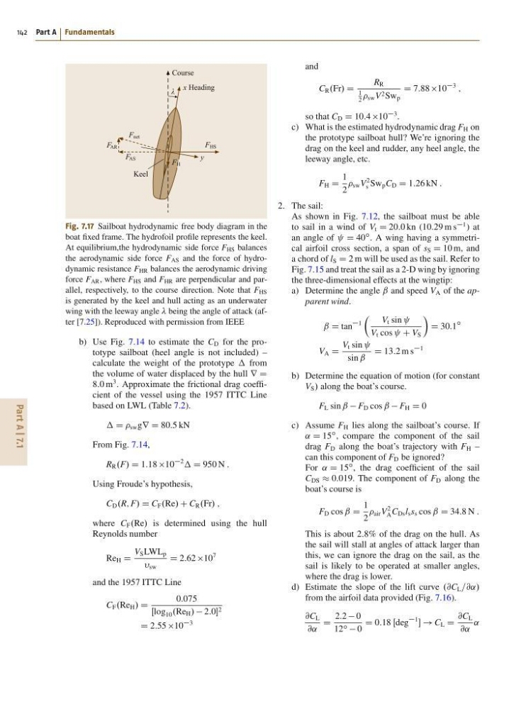
Fig. 7.17 Sailboat hydrodynamic free body diagram in the
boat fixed frame. The hydrofoil profile represents the keel.
At equilibrium,the hydrodynamic side force F HS balances
the aerodynamic side force F AS and the force of hydrodynamic resistance F HR balances the aerodynamic driving
force F AR , where F HS and F HR are perpendicular and parallel, respectively, to the course direction. Note that F HS
is generated by the keel and hull acting as an underwater
wing with the leeway angle being the angle of attack (after [7.25]). Reproduced with permission from IEEE
b) Use Fig. 7.14 to estimate the C D for the prototype sailboat (heel angle is not included) –
calculate the weight of the prototype from
the volume of water displaced by the hull r D
8:0 m
3 . Approximate the frictional drag coefficient of the vessel using the 1957 ITTC Line
based on LWL (Table 7.2).
D sw gr D 80:5 kN
From Fig. 7.14,
R R .F/ D 1:18 10
2
D 950 N :
Using Froude’s hypothesis,
C D .R; F/ D C F .Re/ C C R .Fr/ ;
where C F .Re/ is determined using the hull
Reynolds number
Re H D
V S LWL p
sw
D 2:62 10
7
and the 1957 ITTC Line
C F .Re H / D
0:075
Œlog 10 .Re H / 2:0 2
D 2:55 10
3
and
C R .Fr/ D
R R
1
2
sw V 2 Sw p
D 7:88 10
3
;
so that C D D 10:4 10
3 .
c) What is the estimated hydrodynamic drag F H on
the prototype sailboat hull? We’re ignoring the
drag on the keel and rudder, any heel angle, the
leeway angle, etc.
F H D
1
2
sw V
2
s Sw p C D D 1:26 kN :
2. The sail:
As shown in Fig. 7.12, the sailboat must be able
to sail in a wind of V t D 20:0 kn (10:29 m s
1 ) at
an angle of D 40
ı . A wing having a symmetrical airfoil cross section, a span of s S D 10 m, and
a chord of l S D 2 m will be used as the sail. Refer to
Fig. 7.15 and treat the sail as a 2-D wing by ignoring
the three-dimensional effects at the wingtip:
a) Determine the angle ˇ and speed V A of the apparent wind.
ˇ D tan
1
Â
V t sin
V t cos C V S
Ã
D 30:1
ı
V A D
V t sin
sin ˇ
D 13:2 m s
1
b) Determine the equation of motion (for constant
V S / along the boat’s course.
F L sin ˇ F D cos ˇ F H D 0
c) Assume F H lies along the sailboat’s course. If
˛ D 15
ı , compare the component of the sail
drag F D along the boat’s trajectory with F H –
can this component of F D be ignored?
For ˛ D 15
ı , the drag coefficient of the sail
C DS 0:019. The component of F D along the
boat’s course is
F D cos ˇ D
1
2
air V
2
A C Ds l s s s cos ˇ D 34:8 N :
This is about 2:8% of the drag on the hull. As
the sail will stall at angles of attack larger than
this, we can ignore the drag on the sail, as the
sail is likely to be operated at smaller angles,
where the drag is lower.
d) Estimate the slope of the lift curve .@C L =@˛/
from the airfoil data provided (Fig. 7.16).
@C L
@˛
D
2:2 0
12 ı 0
D 0:18 Œdeg
1
! C L D
@C L
@˛
˛
142 Part A Fundamentals
Course
x Heading
y
F net
F AR
F AS
λ
F H
Keel
F HS
Fig. 7.17 Sailboat hydrodynamic free body diagram in the
boat fixed frame. The hydrofoil profile represents the keel.
At equilibrium,the hydrodynamic side force F HS balances
the aerodynamic side force F AS and the force of hydrodynamic resistance F HR balances the aerodynamic driving
force F AR , where F HS and F HR are perpendicular and parallel, respectively, to the course direction. Note that F HS
is generated by the keel and hull acting as an underwater
wing with the leeway angle being the angle of attack (after [7.25]). Reproduced with permission from IEEE
b) Use Fig. 7.14 to estimate the C D for the prototype sailboat (heel angle is not included) –
calculate the weight of the prototype from
the volume of water displaced by the hull r D
8:0 m
3 . Approximate the frictional drag coefficient of the vessel using the 1957 ITTC Line
based on LWL (Table 7.2).
D sw gr D 80:5 kN
From Fig. 7.14,
R R .F/ D 1:18 10
2
D 950 N :
Using Froude’s hypothesis,
C D .R; F/ D C F .Re/ C C R .Fr/ ;
where C F .Re/ is determined using the hull
Reynolds number
Re H D
V S LWL p
sw
D 2:62 10
7
and the 1957 ITTC Line
C F .Re H / D
0:075
Œlog 10 .Re H / 2:0 2
D 2:55 10
3
and
C R .Fr/ D
R R
1
2
sw V 2 Sw p
D 7:88 10
3
;
so that C D D 10:4 10
3 .
c) What is the estimated hydrodynamic drag F H on
the prototype sailboat hull? We’re ignoring the
drag on the keel and rudder, any heel angle, the
leeway angle, etc.
F H D
1
2
sw V
2
s Sw p C D D 1:26 kN :
2. The sail:
As shown in Fig. 7.12, the sailboat must be able
to sail in a wind of V t D 20:0 kn (10:29 m s
1 ) at
an angle of D 40
ı . A wing having a symmetrical airfoil cross section, a span of s S D 10 m, and
a chord of l S D 2 m will be used as the sail. Refer to
Fig. 7.15 and treat the sail as a 2-D wing by ignoring
the three-dimensional effects at the wingtip:
a) Determine the angle ˇ and speed V A of the apparent wind.
ˇ D tan
1
Â
V t sin
V t cos C V S
Ã
D 30:1
ı
V A D
V t sin
sin ˇ
D 13:2 m s
1
b) Determine the equation of motion (for constant
V S / along the boat’s course.
F L sin ˇ F D cos ˇ F H D 0
c) Assume F H lies along the sailboat’s course. If
˛ D 15
ı , compare the component of the sail
drag F D along the boat’s trajectory with F H –
can this component of F D be ignored?
For ˛ D 15
ı , the drag coefficient of the sail
C DS 0:019. The component of F D along the
boat’s course is
F D cos ˇ D
1
2
air V
2
A C Ds l s s s cos ˇ D 34:8 N :
This is about 2:8% of the drag on the hull. As
the sail will stall at angles of attack larger than
this, we can ignore the drag on the sail, as the
sail is likely to be operated at smaller angles,
where the drag is lower.
d) Estimate the slope of the lift curve .@C L =@˛/
from the airfoil data provided (Fig. 7.16).
@C L
@˛
D
2:2 0
12 ı 0
D 0:18 Œdeg
1
! C L D
@C L
@˛
˛