

Hydromechanics 7.1 Dimensional Analysis, Basic Estimation, and Model Testing 139
Part A | 7.1
Stall – a viscous
effect, Re dependent
Symmetrical
foil
Cambered
foil
10°
C 2 (α=0) = 0
a)
b)
C l
Re 1
Re 2
Re 3
α
10°
–10°
0.005
C d
α
Re increasing
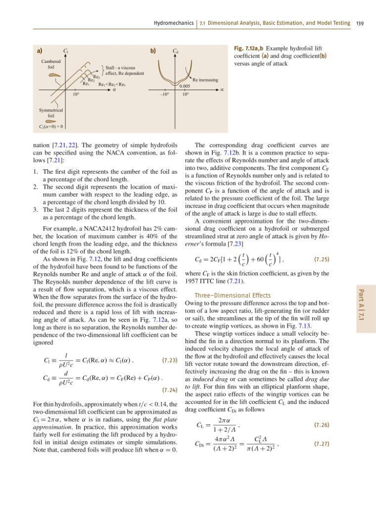
Fig. 7.12a,b Example hydrofoil lift
coefficient (a) and drag coefficient(b)
versus angle of attack
nation [7.21, 22]. The geometry of simple hydrofoils
can be specified using the NACA convention, as follows [7.21]:
1. The first digit represents the camber of the foil as
a percentage of the chord length.
2. The second digit represents the location of maximum camber with respect to the leading edge, as
a percentage of the chord length divided by 10.
3. The last 2 digits represent the thickness of the foil
as a percentage of the chord length.
For example, a NACA2412 hydrofoil has 2% camber, the location of maximum camber is 40% of the
chord length from the leading edge, and the thickness
of the foil is 12% of the chord length.
As shown in Fig. 7.12, the lift and drag coefficients
of the hydrofoil have been found to be functions of the
Reynolds number Re and angle of attack ˛ of the foil.
The Reynolds number dependence of the lift curve is
a result of flow separation, which is a viscous effect.
When the flow separates from the surface of the hydrofoil, the pressure difference across the foil is drastically
reduced and there is a rapid loss of lift with increasing angle of attack. As can be seen in Fig. 7.12a, so
long as there is no separation, the Reynolds number dependence of the two-dimensional lift coefficient can be
ignored
C l Á
l
U 2 c
D C l .Re; ˛/ C l .˛/ ;
(7.23)
C d Á
d
U 2 c
D C d .Re; ˛/ D C F .Re/ C C P .˛/ :
(7.24)
For thin hydrofoils, approximately when t=c < 0:14, the
two-dimensional lift coefficient can be approximated as
C l D 2˛, where ˛ is in radians, using the flat plate
approximation. In practice, this approximation works
fairly well for estimating the lift produced by a hydrofoil in initial design estimates or simple simulations.
Note that, cambered foils will produce lift when ˛ D 0.
The corresponding drag coefficient curves are
shown in Fig. 7.12b. It is a common practice to separate the effects of Reynolds number and angle of attack
into two, additive components. The first component C F
is a function of Reynolds number only and is related to
the viscous friction of the hydrofoil. The second component C P is a function of the angle of attack and is
related to the pressure coefficient of the foil. The large
increase in drag coefficient that occurs when magnitude
of the angle of attack is large is due to stall effects.
A convenient approximation for the two-dimensional drag coefficient on a hydrofoil or submerged
streamlined strut at zero angle of attack is given by Hoerner’s formula [7.23]
C d D 2C F Œ1 C 2
t
c
Á
C 60
t
c
Á 4
;
(7.25)
where C F is the skin friction coefficient, as given by the
1957 ITTC line (7.21).
Three-Dimensional Effects
Owing to the pressure difference across the top and bottom of a low aspect ratio, lift-generating fin (or rudder
or sail), the streamlines at the tip of the fin will roll up
to create wingtip vortices, as shown in Fig. 7.13.
These wingtip vortices induce a small velocity behind the fin in a direction normal to its planform. The
induced velocity changes the local angle of attack of
the flow at the hydrofoil and effectively causes the local
lift vector rotate toward the downstream direction, effectively increasing the drag on the fin – this is known
as induced drag or can sometimes be called drag due
to lift. For thin fins with an elliptical planform shape,
the aspect ratio effects of the wingtip vortices can be
accounted for in the lift coefficient C L and the induced
drag coefficient C Di as follows
C L D
2˛
1 C 2==
;
(7.26)
C Di D
4˛
2
.. C 2/ 2 D
C
2
L
.. C 2/ 2 ;
(7.27)
Part A | 7.1
Stall – a viscous
effect, Re dependent
Symmetrical
foil
Cambered
foil
10°
C 2 (α=0) = 0
a)
b)
C l
Re 1
Re 2
Re 3
α
10°
–10°
0.005
C d
α
Re increasing
Fig. 7.12a,b Example hydrofoil lift
coefficient (a) and drag coefficient(b)
versus angle of attack
nation [7.21, 22]. The geometry of simple hydrofoils
can be specified using the NACA convention, as follows [7.21]:
1. The first digit represents the camber of the foil as
a percentage of the chord length.
2. The second digit represents the location of maximum camber with respect to the leading edge, as
a percentage of the chord length divided by 10.
3. The last 2 digits represent the thickness of the foil
as a percentage of the chord length.
For example, a NACA2412 hydrofoil has 2% camber, the location of maximum camber is 40% of the
chord length from the leading edge, and the thickness
of the foil is 12% of the chord length.
As shown in Fig. 7.12, the lift and drag coefficients
of the hydrofoil have been found to be functions of the
Reynolds number Re and angle of attack ˛ of the foil.
The Reynolds number dependence of the lift curve is
a result of flow separation, which is a viscous effect.
When the flow separates from the surface of the hydrofoil, the pressure difference across the foil is drastically
reduced and there is a rapid loss of lift with increasing angle of attack. As can be seen in Fig. 7.12a, so
long as there is no separation, the Reynolds number dependence of the two-dimensional lift coefficient can be
ignored
C l Á
l
U 2 c
D C l .Re; ˛/ C l .˛/ ;
(7.23)
C d Á
d
U 2 c
D C d .Re; ˛/ D C F .Re/ C C P .˛/ :
(7.24)
For thin hydrofoils, approximately when t=c < 0:14, the
two-dimensional lift coefficient can be approximated as
C l D 2˛, where ˛ is in radians, using the flat plate
approximation. In practice, this approximation works
fairly well for estimating the lift produced by a hydrofoil in initial design estimates or simple simulations.
Note that, cambered foils will produce lift when ˛ D 0.
The corresponding drag coefficient curves are
shown in Fig. 7.12b. It is a common practice to separate the effects of Reynolds number and angle of attack
into two, additive components. The first component C F
is a function of Reynolds number only and is related to
the viscous friction of the hydrofoil. The second component C P is a function of the angle of attack and is
related to the pressure coefficient of the foil. The large
increase in drag coefficient that occurs when magnitude
of the angle of attack is large is due to stall effects.
A convenient approximation for the two-dimensional drag coefficient on a hydrofoil or submerged
streamlined strut at zero angle of attack is given by Hoerner’s formula [7.23]
C d D 2C F Œ1 C 2
t
c
Á
C 60
t
c
Á 4
;
(7.25)
where C F is the skin friction coefficient, as given by the
1957 ITTC line (7.21).
Three-Dimensional Effects
Owing to the pressure difference across the top and bottom of a low aspect ratio, lift-generating fin (or rudder
or sail), the streamlines at the tip of the fin will roll up
to create wingtip vortices, as shown in Fig. 7.13.
These wingtip vortices induce a small velocity behind the fin in a direction normal to its planform. The
induced velocity changes the local angle of attack of
the flow at the hydrofoil and effectively causes the local
lift vector rotate toward the downstream direction, effectively increasing the drag on the fin – this is known
as induced drag or can sometimes be called drag due
to lift. For thin fins with an elliptical planform shape,
the aspect ratio effects of the wingtip vortices can be
accounted for in the lift coefficient C L and the induced
drag coefficient C Di as follows
C L D
2˛
1 C 2==
;
(7.26)
C Di D
4˛
2
.. C 2/ 2 D
C
2
L
.. C 2/ 2 ;
(7.27)