

Part A | 7.1
140 Part A Fundamentals
Streamline along
lower surface
Streamline over
upper surface
Counterclockwise
wingtip vortex
Clockwise
wingtip vortex
Low
pressure
High
pressure
Pressure distribution
Front view
Top view
U
Fig. 7.13 Formation of wingtip vortices at the tips of a fin
or rudder
where the total drag coefficient is the sum of the twodimensional drag coefficient C d and the induced drag
coefficient C Dtot D C d C C Di .
Example 7.6
The following questions pertain to a prototype sailboat
designed for oceanographic measurement [7.24–28].
Some of the model and prototype dimensions are shown
in Table 7.2; properties of air and seawater at design
conditions are given in Table 7.3.
The following questions may be posed:
1. The hullform:
a) The model and prototype sailboats are geometrically similar:
i. Fill-in the missing prototype values in Table 7.2.
ii. The prototype will be operated at Fr D
0:375, where the relevant length scale is
taken as the length on the waterline, LWL
(Table 7.2). What is the design speed V S of
the prototype?
Table 7.2 Model and prototype dimensions
Quantity
Model
Prototype
Length overall (LOA) [m]
2:47
11
Length on waterline (LWL) [m]
2:00
Wetted surface area [m 2 ]
0:965
Table 7.3 Properties of water and air at 15
ı C
Medium
Sea water
Air
Density [kg m 3 ]
1025:9
1:226
Kinematic viscosity [m 2 s 1 ]
1:19 10 6 1:45 10 5
0
0.1
0.2
0.3
0.4
0.5
0.6
R R /Δ
Fr
0.1
0.09
0.08
0.07
0.06
0.05
0.04
0.03
0.02
0.01
0
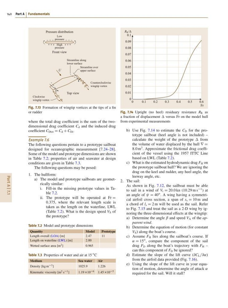
Fig. 7.14 Upright (no heel) residuary resistance R R as
a fraction of displacement versus Fr on the model hull
from experimental measurements
b) Use Fig. 7.14 to estimate the C D for the prototype sailboat (heel angle is not included) –
calculate the weight of the prototype from
the volume of water displaced by the hull r D
8:0 m
3 . Approximate the frictional drag coefficient of the vessel using the 1957 ITTC Line
based on LWL (Table 7.2).
c) What is the estimated hydrodynamic drag F H on
the prototype sailboat hull? We are ignoring the
drag on the keel and rudder, any heel angle, the
leeway angle, etc.
2. The sail:
As shown in Fig. 7.12, the sailboat must be able
to sail in a wind of V t D 20:0 kn (10:29 m s
1 ) at
an angle of D 40
ı . A wing having a symmetrical airfoil cross section, a span of s s D 10 m and
a chord of l s D 2 m will be used as the sail. Refer
to Fig. 7.15 and treat the sail as a 2-D wing by ignoring the three-dimensional effects at the wingtip:
a) Determine the angle ˇ and speed V A of the apparent wind.
b) Determine the equation of motion (for constant
V S / along the boat’s course.
c) Assume F H lies along the sailboat’s course. If
˛ D 15
ı , compare the component of the sail
drag F D along the boat’s trajectory with F H –
can this component of F D be ignored?
d) Estimate the slope of the lift curve (@C L =@˛/
from the airfoil data provided (Fig. 7.16).
e) Using the slope of the lift curve in your equation of motion, determine the angle of attack ˛
required for the sail. Will it stall?
140 Part A Fundamentals
Streamline along
lower surface
Streamline over
upper surface
Counterclockwise
wingtip vortex
Clockwise
wingtip vortex
Low
pressure
High
pressure
Pressure distribution
Front view
Top view
U
Fig. 7.13 Formation of wingtip vortices at the tips of a fin
or rudder
where the total drag coefficient is the sum of the twodimensional drag coefficient C d and the induced drag
coefficient C Dtot D C d C C Di .
Example 7.6
The following questions pertain to a prototype sailboat
designed for oceanographic measurement [7.24–28].
Some of the model and prototype dimensions are shown
in Table 7.2; properties of air and seawater at design
conditions are given in Table 7.3.
The following questions may be posed:
1. The hullform:
a) The model and prototype sailboats are geometrically similar:
i. Fill-in the missing prototype values in Table 7.2.
ii. The prototype will be operated at Fr D
0:375, where the relevant length scale is
taken as the length on the waterline, LWL
(Table 7.2). What is the design speed V S of
the prototype?
Table 7.2 Model and prototype dimensions
Quantity
Model
Prototype
Length overall (LOA) [m]
2:47
11
Length on waterline (LWL) [m]
2:00
Wetted surface area [m 2 ]
0:965
Table 7.3 Properties of water and air at 15
ı C
Medium
Sea water
Air
Density [kg m 3 ]
1025:9
1:226
Kinematic viscosity [m 2 s 1 ]
1:19 10 6 1:45 10 5
0
0.1
0.2
0.3
0.4
0.5
0.6
R R /Δ
Fr
0.1
0.09
0.08
0.07
0.06
0.05
0.04
0.03
0.02
0.01
0
Fig. 7.14 Upright (no heel) residuary resistance R R as
a fraction of displacement versus Fr on the model hull
from experimental measurements
b) Use Fig. 7.14 to estimate the C D for the prototype sailboat (heel angle is not included) –
calculate the weight of the prototype from
the volume of water displaced by the hull r D
8:0 m
3 . Approximate the frictional drag coefficient of the vessel using the 1957 ITTC Line
based on LWL (Table 7.2).
c) What is the estimated hydrodynamic drag F H on
the prototype sailboat hull? We are ignoring the
drag on the keel and rudder, any heel angle, the
leeway angle, etc.
2. The sail:
As shown in Fig. 7.12, the sailboat must be able
to sail in a wind of V t D 20:0 kn (10:29 m s
1 ) at
an angle of D 40
ı . A wing having a symmetrical airfoil cross section, a span of s s D 10 m and
a chord of l s D 2 m will be used as the sail. Refer
to Fig. 7.15 and treat the sail as a 2-D wing by ignoring the three-dimensional effects at the wingtip:
a) Determine the angle ˇ and speed V A of the apparent wind.
b) Determine the equation of motion (for constant
V S / along the boat’s course.
c) Assume F H lies along the sailboat’s course. If
˛ D 15
ı , compare the component of the sail
drag F D along the boat’s trajectory with F H –
can this component of F D be ignored?
d) Estimate the slope of the lift curve (@C L =@˛/
from the airfoil data provided (Fig. 7.16).
e) Using the slope of the lift curve in your equation of motion, determine the angle of attack ˛
required for the sail. Will it stall?