

Part A | 7.1
138 Part A Fundamentals
5. Then the total resistance of the prototype is
C Tp D C Fp CC Rp D C Fp .Re p / CC Tm C Fm .Re m / :
Note that the ITTC line assumes that the flow is
turbulent. For most models, even those of the modest
length (about 1 m), towed at slow speeds (2 kn), the flow
will be turbulent over at least part of the model. However, the geometrically scaled thickness of the boundary
layer about the model will tend to be much thicker
than that about the prototype and the difference can
lead to some discrepancy in the drag predicted using Froude’s hypothesis. To mitigate this, turbulence
stimulators (tripwires, sandpaper, thick tape, etc.) are
often utilized in model testing to ensure that the boundary layer transitions from laminar to turbulent flow as
quickly as possible at the bow of the model. The required thickness of a trip t can be estimated using the
following relation for the critical Reynolds number for
transition [7.20]
Re crit D
Ut
826 :
(7.22)
Note that the selection of trip thickness is a balancing
act between forcing the flow to transition to turbulence
and affecting the pressure distribution about the hull
and thereby affecting the global flow distribution.
7.1.6 Hydrofoil Lift and Drag
Strictly speaking, a hydrofoil is the cross-sectional
shape of a larger rudder, fin or underwater wing. Any
two-dimensional streamlined body that generates lift
can be thought of as a hydrofoil. Here, the lift force
per unit span l is perpendicular to the direction of the
freestream flow (flow undisturbed by the presence of
the hydrofoil) and the drag force d is always parallel
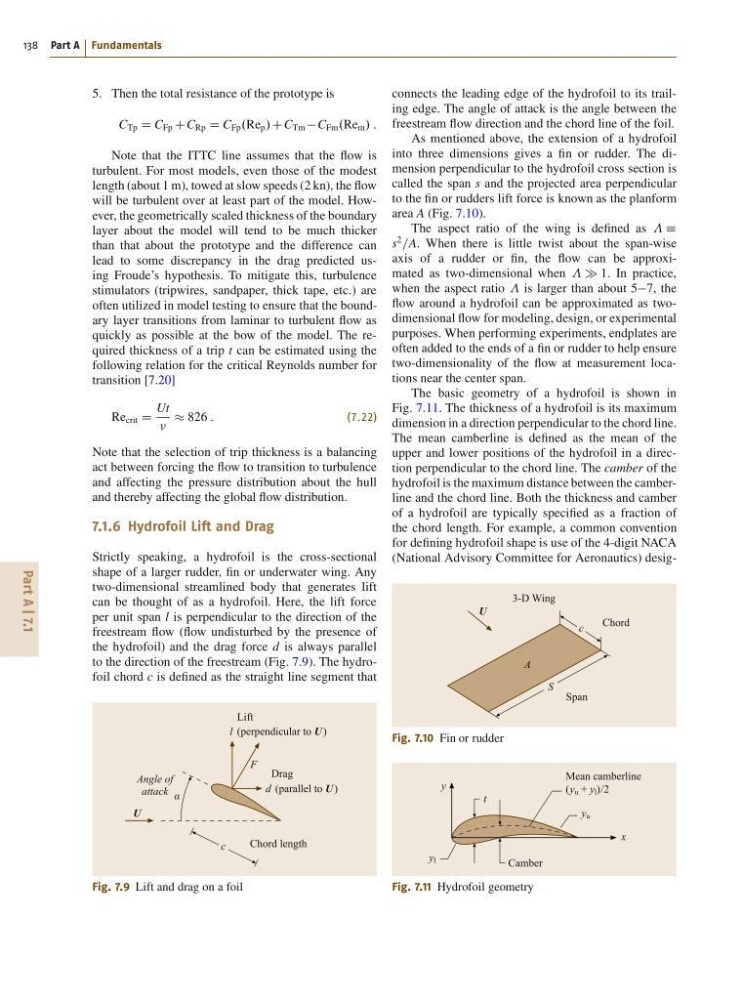
to the direction of the freestream (Fig. 7.9). The hydrofoil chord c is defined as the straight line segment that
Angle of
attack α
U
Lift
Drag
(perpendicular to U )
(parallel to U )
l
F
d
c
Chord length
Fig. 7.9 Lift and drag on a foil
connects the leading edge of the hydrofoil to its trailing edge. The angle of attack is the angle between the
freestream flow direction and the chord line of the foil.
As mentioned above, the extension of a hydrofoil
into three dimensions gives a fin or rudder. The dimension perpendicular to the hydrofoil cross section is
called the span s and the projected area perpendicular
to the fin or rudders lift force is known as the planform
area A (Fig. 7.10).
The aspect ratio of the wing is defined as Á
s
2
=A. When there is little twist about the span-wise
axis of a rudder or fin, the flow can be approximated as two-dimensional when 1. In practice,
when the aspect ratio is larger than about 57, the
flow around a hydrofoil can be approximated as twodimensional flow for modeling, design, or experimental
purposes. When performing experiments, endplates are
often added to the ends of a fin or rudder to help ensure
two-dimensionality of the flow at measurement locations near the center span.
The basic geometry of a hydrofoil is shown in
Fig. 7.11. The thickness of a hydrofoil is its maximum
dimension in a direction perpendicular to the chord line.
The mean camberline is defined as the mean of the
upper and lower positions of the hydrofoil in a direction perpendicular to the chord line. The camber of the
hydrofoil is the maximum distance between the camberline and the chord line. Both the thickness and camber
of a hydrofoil are typically specified as a fraction of
the chord length. For example, a common convention
for defining hydrofoil shape is use of the 4-digit NACA
(National Advisory Committee for Aeronautics) desigU
c
S
A
Chord
3-D Wing
Span
Fig. 7.10 Fin or rudder
Mean camberline
(y u + y l )/2
Camber
y
y l
y u
x
t
Fig. 7.11 Hydrofoil geometry
138 Part A Fundamentals
5. Then the total resistance of the prototype is
C Tp D C Fp CC Rp D C Fp .Re p / CC Tm C Fm .Re m / :
Note that the ITTC line assumes that the flow is
turbulent. For most models, even those of the modest
length (about 1 m), towed at slow speeds (2 kn), the flow
will be turbulent over at least part of the model. However, the geometrically scaled thickness of the boundary
layer about the model will tend to be much thicker
than that about the prototype and the difference can
lead to some discrepancy in the drag predicted using Froude’s hypothesis. To mitigate this, turbulence
stimulators (tripwires, sandpaper, thick tape, etc.) are
often utilized in model testing to ensure that the boundary layer transitions from laminar to turbulent flow as
quickly as possible at the bow of the model. The required thickness of a trip t can be estimated using the
following relation for the critical Reynolds number for
transition [7.20]
Re crit D
Ut
826 :
(7.22)
Note that the selection of trip thickness is a balancing
act between forcing the flow to transition to turbulence
and affecting the pressure distribution about the hull
and thereby affecting the global flow distribution.
7.1.6 Hydrofoil Lift and Drag
Strictly speaking, a hydrofoil is the cross-sectional
shape of a larger rudder, fin or underwater wing. Any
two-dimensional streamlined body that generates lift
can be thought of as a hydrofoil. Here, the lift force
per unit span l is perpendicular to the direction of the
freestream flow (flow undisturbed by the presence of
the hydrofoil) and the drag force d is always parallel
to the direction of the freestream (Fig. 7.9). The hydrofoil chord c is defined as the straight line segment that
Angle of
attack α
U
Lift
Drag
(perpendicular to U )
(parallel to U )
l
F
d
c
Chord length
Fig. 7.9 Lift and drag on a foil
connects the leading edge of the hydrofoil to its trailing edge. The angle of attack is the angle between the
freestream flow direction and the chord line of the foil.
As mentioned above, the extension of a hydrofoil
into three dimensions gives a fin or rudder. The dimension perpendicular to the hydrofoil cross section is
called the span s and the projected area perpendicular
to the fin or rudders lift force is known as the planform
area A (Fig. 7.10).
The aspect ratio of the wing is defined as Á
s
2
=A. When there is little twist about the span-wise
axis of a rudder or fin, the flow can be approximated as two-dimensional when 1. In practice,
when the aspect ratio is larger than about 57, the
flow around a hydrofoil can be approximated as twodimensional flow for modeling, design, or experimental
purposes. When performing experiments, endplates are
often added to the ends of a fin or rudder to help ensure
two-dimensionality of the flow at measurement locations near the center span.
The basic geometry of a hydrofoil is shown in
Fig. 7.11. The thickness of a hydrofoil is its maximum
dimension in a direction perpendicular to the chord line.
The mean camberline is defined as the mean of the
upper and lower positions of the hydrofoil in a direction perpendicular to the chord line. The camber of the
hydrofoil is the maximum distance between the camberline and the chord line. Both the thickness and camber
of a hydrofoil are typically specified as a fraction of
the chord length. For example, a common convention
for defining hydrofoil shape is use of the 4-digit NACA
(National Advisory Committee for Aeronautics) desigU
c
S
A
Chord
3-D Wing
Span
Fig. 7.10 Fin or rudder
Mean camberline
(y u + y l )/2
Camber
y
y l
y u
x
t
Fig. 7.11 Hydrofoil geometry