

353
Airborne Water Vapor Differential Absorption Lidar
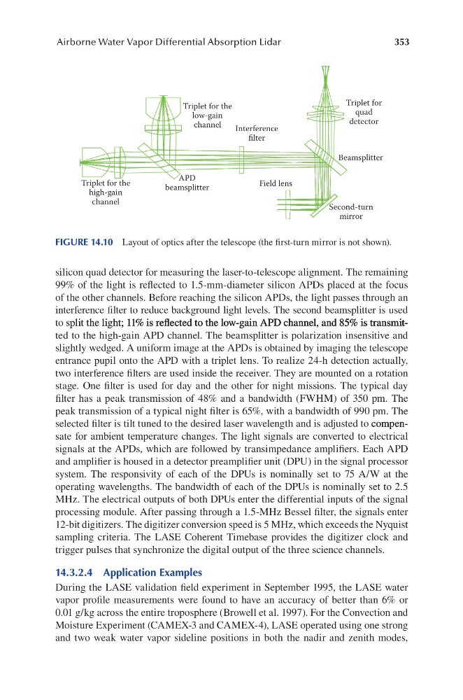
silicon quad detector for measuring the laser-to-telescope alignment. The remaining
99% of the light is reflected to 1.5-mm-diameter silicon APDs placed at the focus
of the other channels. Before reaching the silicon APDs, the light passes through an
interference filter to reduce background light levels. The second beamsplitter is used
to split the light; 11% is refl ected to the low-gain APD channel, and 85% is transmitsplit the light; 11% is refl ected to the low-gain APD channel, and 85% is transmitthe light; 11% is refl ected to the low-gain APD channel, and 85% is transmit; 11% is refl ected to the low-gain APD channel, and 85% is transmit% is refl ected to the low-gain APD channel, and 85% is transmitis reflected to the low-gain APD channel, and 85% is transmit% is transmitis transmitted to the high-gain APD channel. The beamsplitter is polarization insensitive and
slightly wedged. A uniform image at the APDs is obtained by imaging the telescope
entrance pupil onto the APD with a triplet lens. To realize 24-h detection actually,
two interference filters are used inside the receiver. They are mounted on a rotation
stage. One filter is used for day and the other for night missions. The typical day
filter has a peak transmission of 48% and a bandwidth (FWHM) of 350 pm. The
peak transmission of a typical night filter is 65%, with a bandwidth of 990 pm. The
selected filter is tilt tuned to the desired laser wavelength and is adjusted to compen- compen- compensate for ambient temperature changes. The light signals are converted to electrical
signals at the APDs, which are followed by transimpedance amplifiers. Each APD
and amplifier is housed in a detector preamplifier unit (DPU) in the signal processor
system. The responsivity of each of the DPUs is nominally set to 75 A/W at the
operating wavelengths. The bandwidth of each of the DPUs is nominally set to 2.5
MHz. The electrical outputs of both DPUs enter the differential inputs of the signal
processing module. After passing through a 1.5-MHz Bessel filter, the signals enter
12-bit digitizers. The digitizer conversion speed is 5 MHz, which exceeds the Nyquist
sampling criteria. The LASE Coherent Timebase provides the digitizer clock and
trigger pulses that synchronize the digital output of the three science channels.
14.3.2.4 Application Examples
During the LASE validation field experiment in September 1995, the LASE water
vapor profile measurements were found to have an accuracy of better than 6% or
0.01 g/kg across the entire troposphere (Browell et al. 1997). For the Convection and
Moisture Experiment (CAMEX-3 and CAMEX-4), LASE operated using one strong
and two weak water vapor sideline positions in both the nadir and zenith modes,
Triplet for the
high-gain
channel
Triplet for the
low-gain
channel
Triplet for
quad
detector
Interference
filter
Field lens
APD
beamsplitter
Beamsplitter
Second-turn
mirror
FIGURE 14.10 Layout of optics after the telescope (the first-turn mirror is not shown).
Airborne Water Vapor Differential Absorption Lidar
silicon quad detector for measuring the laser-to-telescope alignment. The remaining
99% of the light is reflected to 1.5-mm-diameter silicon APDs placed at the focus
of the other channels. Before reaching the silicon APDs, the light passes through an
interference filter to reduce background light levels. The second beamsplitter is used
to split the light; 11% is refl ected to the low-gain APD channel, and 85% is transmitsplit the light; 11% is refl ected to the low-gain APD channel, and 85% is transmitthe light; 11% is refl ected to the low-gain APD channel, and 85% is transmit; 11% is refl ected to the low-gain APD channel, and 85% is transmit% is refl ected to the low-gain APD channel, and 85% is transmitis reflected to the low-gain APD channel, and 85% is transmit% is transmitis transmitted to the high-gain APD channel. The beamsplitter is polarization insensitive and
slightly wedged. A uniform image at the APDs is obtained by imaging the telescope
entrance pupil onto the APD with a triplet lens. To realize 24-h detection actually,
two interference filters are used inside the receiver. They are mounted on a rotation
stage. One filter is used for day and the other for night missions. The typical day
filter has a peak transmission of 48% and a bandwidth (FWHM) of 350 pm. The
peak transmission of a typical night filter is 65%, with a bandwidth of 990 pm. The
selected filter is tilt tuned to the desired laser wavelength and is adjusted to compen- compen- compensate for ambient temperature changes. The light signals are converted to electrical
signals at the APDs, which are followed by transimpedance amplifiers. Each APD
and amplifier is housed in a detector preamplifier unit (DPU) in the signal processor
system. The responsivity of each of the DPUs is nominally set to 75 A/W at the
operating wavelengths. The bandwidth of each of the DPUs is nominally set to 2.5
MHz. The electrical outputs of both DPUs enter the differential inputs of the signal
processing module. After passing through a 1.5-MHz Bessel filter, the signals enter
12-bit digitizers. The digitizer conversion speed is 5 MHz, which exceeds the Nyquist
sampling criteria. The LASE Coherent Timebase provides the digitizer clock and
trigger pulses that synchronize the digital output of the three science channels.
14.3.2.4 Application Examples
During the LASE validation field experiment in September 1995, the LASE water
vapor profile measurements were found to have an accuracy of better than 6% or
0.01 g/kg across the entire troposphere (Browell et al. 1997). For the Convection and
Moisture Experiment (CAMEX-3 and CAMEX-4), LASE operated using one strong
and two weak water vapor sideline positions in both the nadir and zenith modes,
Triplet for the
high-gain
channel
Triplet for the
low-gain
channel
Triplet for
quad
detector
Interference
filter
Field lens
APD
beamsplitter
Beamsplitter
Second-turn
mirror
FIGURE 14.10 Layout of optics after the telescope (the first-turn mirror is not shown).