

483
14.2
Hydrate Crystal Chemistry and Stability of Gas Hydrates
Table 14.1 Summary of some characteristics from the three crystal hydrate structures (from Sloan 1998).
* = Estimates of structure H cavities from geometric models.
numbers of naturally occurring gas hydrates are highly
variable, and are generally depleted in gas relative to
its stoichiometric value. Samples from the Middle
America trench off Guatemala and from the Green Canyon area of the northern Gulf of Mexico have hydration
numbers of 5.91 and 8.2, respectively (Handa 1990).
Matsumoto et al. (2000) reports a hydration number of
6.2 for hydrate from the Blake Ridge.
14.2.2 Guest Molecules
Gas molecules in sufficient amount are a prerequisite
to stabilize the hydrate structures. In principle, the
occupied hydrate cage is a function of the size ratio of
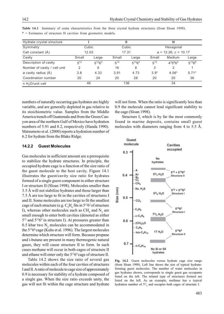
the guest molecule to the host cavity. Figure 14.1
illustrates the guest/cavity size ratio for hydrates
formed of a single guest component in either structure
I or structure II (Sloan 1998). Molecules smaller than
3.5 Å will not stabilize hydrates and those larger than
7.5 Å are too large to fit in the cavities of structures I
and II. Some molecules are too large to fit the smallest
cage of each structure (e.g. C 2 H 6 fits in 5
12
6
2
of structure
I), whereas other molecules such as CH 4 and N 2 are
small enough to enter both cavities (denoted as either
5
12
and 5
12
6
4
in structure I). At pressures greater than
0.5 kbar two N 2 molecules can be accommodated in
the 5
12
6
4
cage (Kuhs et al. 1996). The largest molecules
determine which structure will form. Because propane
and i-butane are present in many thermogenic natural
gases, they will cause structure II to form. In such
cases methane will occur in both cages of structure II
and ethane will enter only the 5
12
6
4
cage of structure II.
Table 14.2 shows the size ratio of several gas
molecules within each of the four cavities of structures
I and II. A ratio of molecule to cage size of approximately
0.9 is necessary for stability of a hydrate composed of
a single gas. When the size ratio exceeds unity, the
gas will not fit within the cage structure and hydrate
will not form. When the ratio is significantly less than
0.9 the molecule cannot lend significant stability to
the cage (Sloan 1998).
Structure I, which is by far the most commonly
found in marine deposits, contains small guest
molecules with diameters ranging from 4 to 5.5 Å.
Hydrate crystal structure
Symmetry
Cell constant (Å)
Cavity
Small
Large
Small
Large
Small
Medium
Large
Description of cavity
5
12
5
12 6
2
5
12
5
12 6
4
5
12
4
3 5
6 6
3
5
12 6
8
N u m b e r o f c a v i t y / c e l l u n i t
2
6
1 6
8
3
2
1
ø cavity radius (Å)
3.8
4.33
3.91
4.73
3.9*
4.06*
5.71*
Coordination number
20
24
20
28
20
20
36
n H 2 O/unit cell
12.03
17.31
a = 12.26; c = 10.17
46
136
34
I
I I
H
Cubic
Cubic
Hexagonal
Fig. 14.2 Guest molecules versus hydrate cage size range
(from Sloan 1998). Left line shows the size of typical hydrateforming guest molecules. The number of water molecules in
gas hydrates shown, corresponds to single guest gas occupants
listed on the left. The related type of structures formed are
listed on the left. As an example, methane has a typical
hydration number of 5
3
/ 4 and occupies both cages of structure I.
14.2
Hydrate Crystal Chemistry and Stability of Gas Hydrates
Table 14.1 Summary of some characteristics from the three crystal hydrate structures (from Sloan 1998).
* = Estimates of structure H cavities from geometric models.
numbers of naturally occurring gas hydrates are highly
variable, and are generally depleted in gas relative to
its stoichiometric value. Samples from the Middle
America trench off Guatemala and from the Green Canyon area of the northern Gulf of Mexico have hydration
numbers of 5.91 and 8.2, respectively (Handa 1990).
Matsumoto et al. (2000) reports a hydration number of
6.2 for hydrate from the Blake Ridge.
14.2.2 Guest Molecules
Gas molecules in sufficient amount are a prerequisite
to stabilize the hydrate structures. In principle, the
occupied hydrate cage is a function of the size ratio of
the guest molecule to the host cavity. Figure 14.1
illustrates the guest/cavity size ratio for hydrates
formed of a single guest component in either structure
I or structure II (Sloan 1998). Molecules smaller than
3.5 Å will not stabilize hydrates and those larger than
7.5 Å are too large to fit in the cavities of structures I
and II. Some molecules are too large to fit the smallest
cage of each structure (e.g. C 2 H 6 fits in 5
12
6
2
of structure
I), whereas other molecules such as CH 4 and N 2 are
small enough to enter both cavities (denoted as either
5
12
and 5
12
6
4
in structure I). At pressures greater than
0.5 kbar two N 2 molecules can be accommodated in
the 5
12
6
4
cage (Kuhs et al. 1996). The largest molecules
determine which structure will form. Because propane
and i-butane are present in many thermogenic natural
gases, they will cause structure II to form. In such
cases methane will occur in both cages of structure II
and ethane will enter only the 5
12
6
4
cage of structure II.
Table 14.2 shows the size ratio of several gas
molecules within each of the four cavities of structures
I and II. A ratio of molecule to cage size of approximately
0.9 is necessary for stability of a hydrate composed of
a single gas. When the size ratio exceeds unity, the
gas will not fit within the cage structure and hydrate
will not form. When the ratio is significantly less than
0.9 the molecule cannot lend significant stability to
the cage (Sloan 1998).
Structure I, which is by far the most commonly
found in marine deposits, contains small guest
molecules with diameters ranging from 4 to 5.5 Å.
Hydrate crystal structure
Symmetry
Cell constant (Å)
Cavity
Small
Large
Small
Large
Small
Medium
Large
Description of cavity
5
12
5
12 6
2
5
12
5
12 6
4
5
12
4
3 5
6 6
3
5
12 6
8
N u m b e r o f c a v i t y / c e l l u n i t
2
6
1 6
8
3
2
1
ø cavity radius (Å)
3.8
4.33
3.91
4.73
3.9*
4.06*
5.71*
Coordination number
20
24
20
28
20
20
36
n H 2 O/unit cell
12.03
17.31
a = 12.26; c = 10.17
46
136
34
I
I I
H
Cubic
Cubic
Hexagonal
Fig. 14.2 Guest molecules versus hydrate cage size range
(from Sloan 1998). Left line shows the size of typical hydrateforming guest molecules. The number of water molecules in
gas hydrates shown, corresponds to single guest gas occupants
listed on the left. The related type of structures formed are
listed on the left. As an example, methane has a typical
hydration number of 5
3
/ 4 and occupies both cages of structure I.