

Ground-Based Remote Sensing of Cloud Properties ...
where
S(i,i) = {
N
{ Nbinmax,
inbin[i] = Nori~ [.]
1nb'ln Z
if Nbinmax ~ Ni,:t!n[i],
if Ni':t!n[i] ~ Nbinmax,
IN::;!n[i] DIVNbinmax + 1 if j < (Ni':;fn[i]%Nbinmax),
J N::t!n[i] DIV Nbinmax if j 2: (N::;fn[i]%Nbinmax),
341
(13.52b)
(13.52c)
V(i,i) , rU,i) and Wd,(i,i) are properties attributed to the ph particle in the ith bin, and 4>.,i is
the phase shift upon scattering from particle sizes corresponding to the ith bin. The operation
DIV implies integer division with no remainder and % stands for the modulo operation. For
the results we present here Nbinmax = 1000. The set of equations (13.52) attempts to produce
the same fluctuations and magnitudes in the f voltages as the exact expression (13.51). The
motivation for this scheme is the observation that nearly identical distributions of voltages over
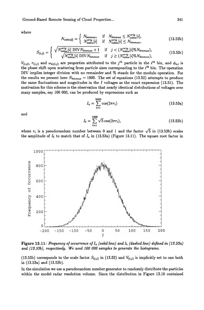
many samples, say 100 000, can be produced by expressions such as
5000
fa = L COS(211Ti)
(13.53a)
i=l
and
1000
fb = L J5 COS(211Ti),
(13.53b)
i=l
where ri is a pseudorandom number between 0 and 1 and the factor J5 in (13.53b) scales
the amplitude of h to match that of fa in (13.53a) (Figure 13.11). The square root factor in
1000
Q)
u
800
c
Q)
l-<
l-<
;:l
u
600
u
0
....
0
>. 400
u
c Q)
~
Q)
200
l-<
r..
a
- 200 -150 -100
- 50
a
50
100
150
200
I
Figure 13.11: Frequency of occurrence of fa (solid line) and h (dashed line) defined in (19.59a)
and (19.59b), respectively. We used 100 000 samples to generate the histograms.
(13.53b) corresponds to the scale factor SU,i) in (13.52) and V(i,i) is implicitly set to one both
in (13.53a) and (13.53b).
In the simulation we use a pseudorandom number generator to randomly distribute the particles
within the model radar resolution volume. Since the distribution in Figure 13.10 contained
where
S(i,i) = {
N
{ Nbinmax,
inbin[i] = Nori~ [.]
1nb'ln Z
if Nbinmax ~ Ni,:t!n[i],
if Ni':t!n[i] ~ Nbinmax,
IN::;!n[i] DIVNbinmax + 1 if j < (Ni':;fn[i]%Nbinmax),
J N::t!n[i] DIV Nbinmax if j 2: (N::;fn[i]%Nbinmax),
341
(13.52b)
(13.52c)
V(i,i) , rU,i) and Wd,(i,i) are properties attributed to the ph particle in the ith bin, and 4>.,i is
the phase shift upon scattering from particle sizes corresponding to the ith bin. The operation
DIV implies integer division with no remainder and % stands for the modulo operation. For
the results we present here Nbinmax = 1000. The set of equations (13.52) attempts to produce
the same fluctuations and magnitudes in the f voltages as the exact expression (13.51). The
motivation for this scheme is the observation that nearly identical distributions of voltages over
many samples, say 100 000, can be produced by expressions such as
5000
fa = L COS(211Ti)
(13.53a)
i=l
and
1000
fb = L J5 COS(211Ti),
(13.53b)
i=l
where ri is a pseudorandom number between 0 and 1 and the factor J5 in (13.53b) scales
the amplitude of h to match that of fa in (13.53a) (Figure 13.11). The square root factor in
1000
Q)
u
800
c
Q)
l-<
l-<
;:l
u
600
u
0
....
0
>. 400
u
c Q)
~
Q)
200
l-<
r..
a
- 200 -150 -100
- 50
a
50
100
150
200
I
Figure 13.11: Frequency of occurrence of fa (solid line) and h (dashed line) defined in (19.59a)
and (19.59b), respectively. We used 100 000 samples to generate the histograms.
(13.53b) corresponds to the scale factor SU,i) in (13.52) and V(i,i) is implicitly set to one both
in (13.53a) and (13.53b).
In the simulation we use a pseudorandom number generator to randomly distribute the particles
within the model radar resolution volume. Since the distribution in Figure 13.10 contained