

Ground-Based Remote Sensing of Cloud Properties ...
'tpw
-- Ilf---------,-----------.. I
~ Distance
o
I
o
I
o
(a)
(b)
(c)
cto
0-c to
-E;l-cto
r- ---------------------------~ Distance
~ Distance
f--r------------- ----- ---- - - - - - - - - - ---.~I --~~ Distance
O c t o
(d)
335
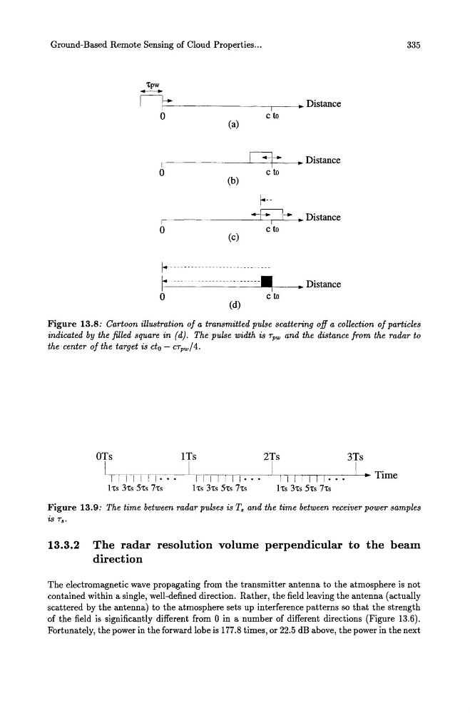
Figure 13.8: Cartoon illustration of a transmitted pulse scattering off a collection of particles
indicated by the filled square in (d). The pulse width is Tpw and the distance from the radar to
the center of the target is cto - cTpw /4.
OTs
1 Ts
2Ts
3Ts
IL._-,-,-,--,--,--,--~I__,_,_,_,__,__,_,________----1.1 ~--r-r-r--,---------LI_.. Tl' me
TIIIIII···
1111111··
1111111··
~
1 'ts 3'ts 5'ts 7'ts
1 'ts 3'ts 5'ts 7'ts
Its 3'ts 5'ts 7'ts
Figure 13.9: The time between radar pulses is T. and the time between receiver power samples
is T •.
13.3.2 The radar resolution volume perpendicular to the beam
direction
The electromagnetic wave propagating from the transmitter antenna to the atmosphere is not
contained within a single, well-defined direction. Rather, the field leaving the antenna (actually
scattered by the antenna) to the atmosphere sets up interference patterns so that the strength
of the field is significantly different from 0 in a number of different directions (Figure 13.6).
Fortunately, the power in the forward lobe is 177.8 times, or 22.5 dB above, the power in the next
'tpw
-- Ilf---------,-----------.. I
~ Distance
o
I
o
I
o
(a)
(b)
(c)
cto
0-c to
-E;l-cto
r- ---------------------------~ Distance
~ Distance
f--r------------- ----- ---- - - - - - - - - - ---.~I --~~ Distance
O c t o
(d)
335
Figure 13.8: Cartoon illustration of a transmitted pulse scattering off a collection of particles
indicated by the filled square in (d). The pulse width is Tpw and the distance from the radar to
the center of the target is cto - cTpw /4.
OTs
1 Ts
2Ts
3Ts
IL._-,-,-,--,--,--,--~I__,_,_,_,__,__,_,________----1.1 ~--r-r-r--,---------LI_.. Tl' me
TIIIIII···
1111111··
1111111··
~
1 'ts 3'ts 5'ts 7'ts
1 'ts 3'ts 5'ts 7'ts
Its 3'ts 5'ts 7'ts
Figure 13.9: The time between radar pulses is T. and the time between receiver power samples
is T •.
13.3.2 The radar resolution volume perpendicular to the beam
direction
The electromagnetic wave propagating from the transmitter antenna to the atmosphere is not
contained within a single, well-defined direction. Rather, the field leaving the antenna (actually
scattered by the antenna) to the atmosphere sets up interference patterns so that the strength
of the field is significantly different from 0 in a number of different directions (Figure 13.6).
Fortunately, the power in the forward lobe is 177.8 times, or 22.5 dB above, the power in the next