

336
Eugene E. Clothiaux, Thomas P. Ackerman, David M. Babb
most significant side lobe. For all practical purposes, therefore, the side lobes can be neglected
in power calculations without introducing significant error. For example, the derivation of
(13.25) is based on a single, Gaussian-shaped antenna beam in the forward direction. The side
lobes can lead to returned power from objects that are located to the side of the radar, which
can be problematic; however, these ground clutter issues are insignificant for the Penn State
radar since the beam is narrow. The nonzero width of the beam within the main lobe leads to
a resolution volume that increases in size with distance from the radar.
13.4 The Radar Receiver
13.4.1 Signal transformations in the radar receiver
From the receiver antenna output port the electromagnetic radiation propagates along a short
stretch of waveguide to the mixer/preamplifier assembly. In the mixer/preamplifier unit the
physical nature of the signal is transformed from a time-dependent, transverse electromagnetic
wave at the input to a time-dependent voltage at the output which is subsequently passed
through the rest of the signal processing chain by coaxial cable. Furthermore, the high carrier
frequency We is transformed to a much lower intermediate frequency Wi. We write the signal
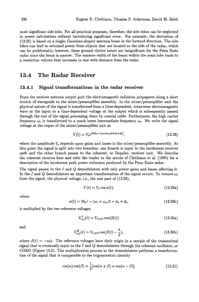
voltage at the ouput of the mixer/preamplifier unit as
(13.28)
where the amplitude V. depends upon gains and losses in the mixer/preamplifier assembly. At
this point the signal is split into two branches: one branch is input to the incoherent receiver
path and the other branch passes to the coherent, or Doppler, receiver unit. We describe
the coherent receiver here and refer the reader to the article of Clothiaux et al. (1995) for a
description of the incoherent path power estimates produced by the Penn State radar.
The signal passes to the I and Q demodulators with only power gains and losses affecting it.
In the I and Q demodulators an important transformation of the signal occurs. To remove Wi
from the signal, the physical voltage, i.e., the real part of (13.28),
V(t) = v. cos a(t),
where
a(t) = 2ker - (Wi + wm)t + 4>. + 4>t,
is mulitplied by the two reference voltages
v,.~/(t) = Y,.e/,Q cos(fJ(t))
and
(13.29a)
(13.29b)
(13.30a)
(13.30b)
where fJ(t) = -Wit. The reference voltages have their origin in a sample of the transmitted
signal that is eventually input to the I and Q demodulators through the coherent oscillator, or
COHO (Figure 13.2). The multiplication process in the demodulators performs a transformation of the signal that is comparable to the trigonometric identity
1
cos(a) cos(fJ) = 2'[cos(a + fJ) + cos(a - fJ)]·
(13.31 )
Eugene E. Clothiaux, Thomas P. Ackerman, David M. Babb
most significant side lobe. For all practical purposes, therefore, the side lobes can be neglected
in power calculations without introducing significant error. For example, the derivation of
(13.25) is based on a single, Gaussian-shaped antenna beam in the forward direction. The side
lobes can lead to returned power from objects that are located to the side of the radar, which
can be problematic; however, these ground clutter issues are insignificant for the Penn State
radar since the beam is narrow. The nonzero width of the beam within the main lobe leads to
a resolution volume that increases in size with distance from the radar.
13.4 The Radar Receiver
13.4.1 Signal transformations in the radar receiver
From the receiver antenna output port the electromagnetic radiation propagates along a short
stretch of waveguide to the mixer/preamplifier assembly. In the mixer/preamplifier unit the
physical nature of the signal is transformed from a time-dependent, transverse electromagnetic
wave at the input to a time-dependent voltage at the output which is subsequently passed
through the rest of the signal processing chain by coaxial cable. Furthermore, the high carrier
frequency We is transformed to a much lower intermediate frequency Wi. We write the signal
voltage at the ouput of the mixer/preamplifier unit as
(13.28)
where the amplitude V. depends upon gains and losses in the mixer/preamplifier assembly. At
this point the signal is split into two branches: one branch is input to the incoherent receiver
path and the other branch passes to the coherent, or Doppler, receiver unit. We describe
the coherent receiver here and refer the reader to the article of Clothiaux et al. (1995) for a
description of the incoherent path power estimates produced by the Penn State radar.
The signal passes to the I and Q demodulators with only power gains and losses affecting it.
In the I and Q demodulators an important transformation of the signal occurs. To remove Wi
from the signal, the physical voltage, i.e., the real part of (13.28),
V(t) = v. cos a(t),
where
a(t) = 2ker - (Wi + wm)t + 4>. + 4>t,
is mulitplied by the two reference voltages
v,.~/(t) = Y,.e/,Q cos(fJ(t))
and
(13.29a)
(13.29b)
(13.30a)
(13.30b)
where fJ(t) = -Wit. The reference voltages have their origin in a sample of the transmitted
signal that is eventually input to the I and Q demodulators through the coherent oscillator, or
COHO (Figure 13.2). The multiplication process in the demodulators performs a transformation of the signal that is comparable to the trigonometric identity
1
cos(a) cos(fJ) = 2'[cos(a + fJ) + cos(a - fJ)]·
(13.31 )