

Ground-Based Remote Sensing of Cloud Properties ...
329
J Pr
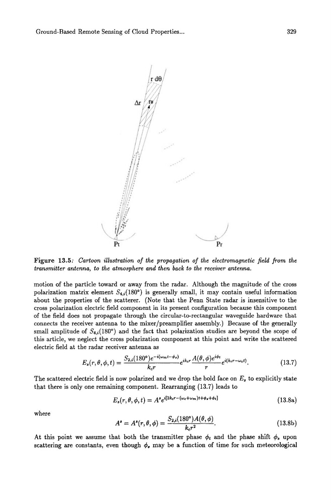
Figure 13.5: Cartoon illustration of the propagation of the electromagnetic field from the
transmitter antenna, to the atmosphere and then back to the receiver antenna.
motion of the particle toward or away from the radar. Although the magnitude of the cross
polarization matrix element 84,i(1800) is generally small, it may contain useful information
about the properties of the scatterer. (Note that the Penn State radar is insensitive to the
cross polarization electric field component in its present configuration because this component
of the field does not propagate through the circular-to-rectangular waveguide hardware that
connects the receiver antenna to the mixer/preamplifier assembly.) Because of the generally
small amplitude of 84,i(1800) and the fact that polarization studies are beyond the scope of
this article, we neglect the cross polarization component at this point and write the scattered
electric field at the radar receiver antenna as
8 '(180°) -i(wmt -¢.)
A(B A.) i¢t
E ( B cP t) - 2,.
e
i k e r ' 'I' e
i(ker-wet )
• r, , , -
kc r
e r e
.
(13.7)
The scattered electric field is now polarized and we drop the bold face on E. to explicitly state
that there is only one remaining component. Rearranging (13.7) leads to
(13.8a)
where
(13.8b)
At this point we assume that both the transmitter phase cPt and the phase shift ¢. upon
scattering are constants, even though cP. may be a function of time for such meteorological
329
J Pr
Figure 13.5: Cartoon illustration of the propagation of the electromagnetic field from the
transmitter antenna, to the atmosphere and then back to the receiver antenna.
motion of the particle toward or away from the radar. Although the magnitude of the cross
polarization matrix element 84,i(1800) is generally small, it may contain useful information
about the properties of the scatterer. (Note that the Penn State radar is insensitive to the
cross polarization electric field component in its present configuration because this component
of the field does not propagate through the circular-to-rectangular waveguide hardware that
connects the receiver antenna to the mixer/preamplifier assembly.) Because of the generally
small amplitude of 84,i(1800) and the fact that polarization studies are beyond the scope of
this article, we neglect the cross polarization component at this point and write the scattered
electric field at the radar receiver antenna as
8 '(180°) -i(wmt -¢.)
A(B A.) i¢t
E ( B cP t) - 2,.
e
i k e r ' 'I' e
i(ker-wet )
• r, , , -
kc r
e r e
.
(13.7)
The scattered electric field is now polarized and we drop the bold face on E. to explicitly state
that there is only one remaining component. Rearranging (13.7) leads to
(13.8a)
where
(13.8b)
At this point we assume that both the transmitter phase cPt and the phase shift ¢. upon
scattering are constants, even though cP. may be a function of time for such meteorological