

328
Eugene E. Clothiaux, Thomas P. Ackerman, David M. Babb
y
a= 2.5 mm
x
(a)
Direction of propagation
of the wave
" Direction of electric
,,~ field vector
> "- " - ',,(b)
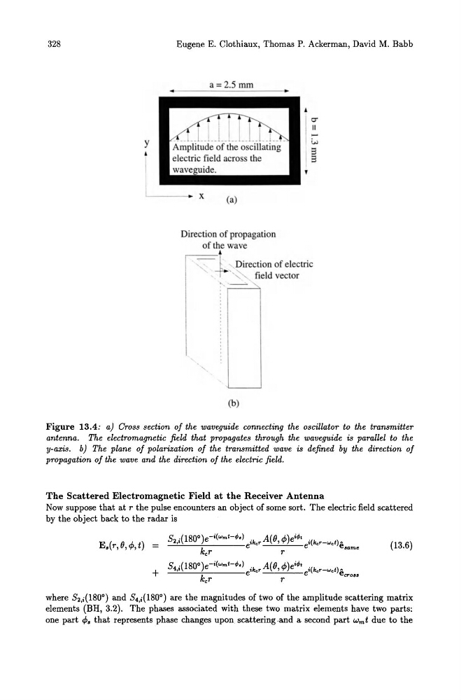
Figure 13.4: a) Cross section of the waveguide connecting the oscillator to the transmitter
antenna. The electromagnetic field that propagates through the waveguide is parallel to the
y-axis. b) The plane of polarization of the transmitted wave is defined by the direction of
propagation of the wave and the direction of the electric field.
The Scattered Electromagnetic Field at the Receiver Antenna
Now suppose that at r the pulse encounters an object of some sort. The electric field scattered
by the object back to the radar is
S2,i(1800)e- i (wm t -tP.) ike r A( e, 4»e itPt i(ker-wet) A
E.(r,e,4>,t) =
k
e
e
e.am•
cr
r
(13.6)
where S2,i(1800) and S4,i(1800) are the magnitudes of two of the amplitude scattering matrix
elements (BH, 3.2). The phases associated with these two matrix elements have two parts:
one part 4>. that represents phase changes upon scattering.and a second part wmt due to the
Eugene E. Clothiaux, Thomas P. Ackerman, David M. Babb
y
a= 2.5 mm
x
(a)
Direction of propagation
of the wave
" Direction of electric
,,~ field vector
> "- " - ',,(b)
Figure 13.4: a) Cross section of the waveguide connecting the oscillator to the transmitter
antenna. The electromagnetic field that propagates through the waveguide is parallel to the
y-axis. b) The plane of polarization of the transmitted wave is defined by the direction of
propagation of the wave and the direction of the electric field.
The Scattered Electromagnetic Field at the Receiver Antenna
Now suppose that at r the pulse encounters an object of some sort. The electric field scattered
by the object back to the radar is
S2,i(1800)e- i (wm t -tP.) ike r A( e, 4»e itPt i(ker-wet) A
E.(r,e,4>,t) =
k
e
e
e.am•
cr
r
(13.6)
where S2,i(1800) and S4,i(1800) are the magnitudes of two of the amplitude scattering matrix
elements (BH, 3.2). The phases associated with these two matrix elements have two parts:
one part 4>. that represents phase changes upon scattering.and a second part wmt due to the