

330
Eugene E. Clothiaux, Thomas P. Ackerman, David M. Babb
30
rg
)..j
20
Q)
:;:
o
p..
10
o~~~~~~~~~~~~~~~~~~~~~~~~
-3
-2
-1
o
1
2
3
Theta (Degrees)
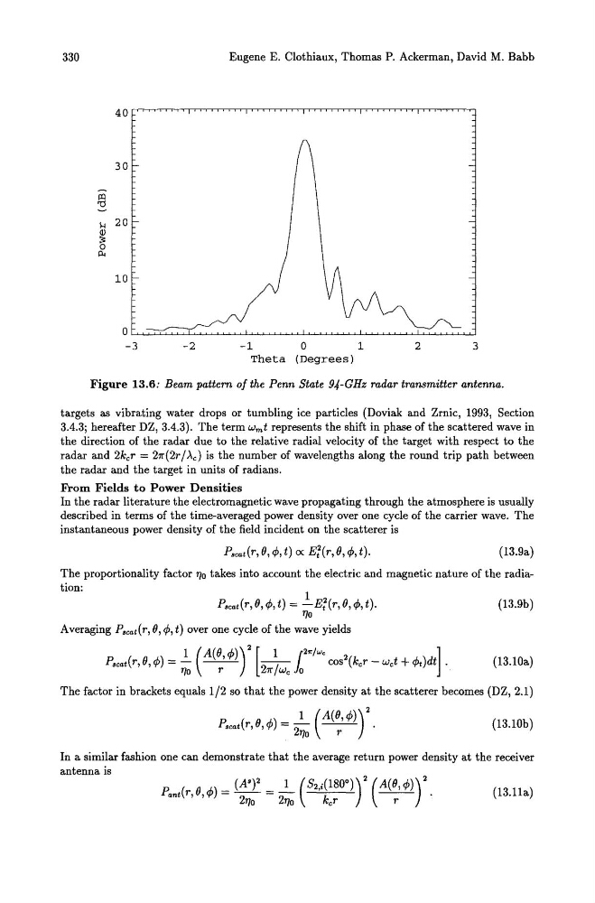
Figure 13.6: Beam pattern of the Penn State 94-GHz radar transmitter antenna.
targets as vibrating water drops or tumbling ice particles (Doviak and Zrnic, 1993, Section
3.4.3; hereafter DZ, 3.4.3). The term wmt represents the shift in phase of the scattered wave in
the direction of the radar due to the relative radial velocity of the target with respect to the
radar and 2kcr = 27r(2r / .xc) is the number of wavelengths along the round trip path between
the radar and the target in units of radians.
From Fields to Power Densities
In the radar literature the electromagnetic wave propagating through the atmosphere is usually
described in terms of the time-averaged power density over one cycle of the carrier wave. The
instantaneous power density of the field incident on the scatterer is
Pscat(r, (}, , t) ex E;(r, (}, , t).
(13.9a)
The proportionality factor "10 takes into account the electric and magnetic nature of the radiation:
Pseat(r, (}, ,t) = l..-E;(r,(},,t).
"10
Averaging Pscat (r, (}, , t) over one cycle of the wave yields
1 (A((}, ]
Pscat(r, 0, t)dt .
(13.9b)
(13.10a)
The factor in brackets equals 1/2 so that the power density at the scatterer becomes (DZ, 2.1)
1 (A(O, Pscat(r, 0, In a similar fashion one can demonstrate that the average return power density at the receiver
antenna is
(13.11a)
Eugene E. Clothiaux, Thomas P. Ackerman, David M. Babb
30
rg
)..j
20
Q)
:;:
o
p..
10
o~~~~~~~~~~~~~~~~~~~~~~~~
-3
-2
-1
o
1
2
3
Theta (Degrees)
Figure 13.6: Beam pattern of the Penn State 94-GHz radar transmitter antenna.
targets as vibrating water drops or tumbling ice particles (Doviak and Zrnic, 1993, Section
3.4.3; hereafter DZ, 3.4.3). The term wmt represents the shift in phase of the scattered wave in
the direction of the radar due to the relative radial velocity of the target with respect to the
radar and 2kcr = 27r(2r / .xc) is the number of wavelengths along the round trip path between
the radar and the target in units of radians.
From Fields to Power Densities
In the radar literature the electromagnetic wave propagating through the atmosphere is usually
described in terms of the time-averaged power density over one cycle of the carrier wave. The
instantaneous power density of the field incident on the scatterer is
Pscat(r, (}, , t) ex E;(r, (}, , t).
(13.9a)
The proportionality factor "10 takes into account the electric and magnetic nature of the radiation:
Pseat(r, (}, ,t) = l..-E;(r,(},,t).
"10
Averaging Pscat (r, (}, , t) over one cycle of the wave yields
1 (A((}, ]
Pscat(r, 0, t)dt .
(13.9b)
(13.10a)
The factor in brackets equals 1/2 so that the power density at the scatterer becomes (DZ, 2.1)
1 (A(O, Pscat(r, 0, In a similar fashion one can demonstrate that the average return power density at the receiver
antenna is
(13.11a)