

326
Eugene E. Clothiaux, Thomas P. Ackerman, David M. Babb
Receive Antenna
r-------------------------------l
I
I
I
I
I
~~~~~~~~~~~~~~~~~==~~~~I: I
'-=--'-'-'''T-'-''="",-, I
I
I
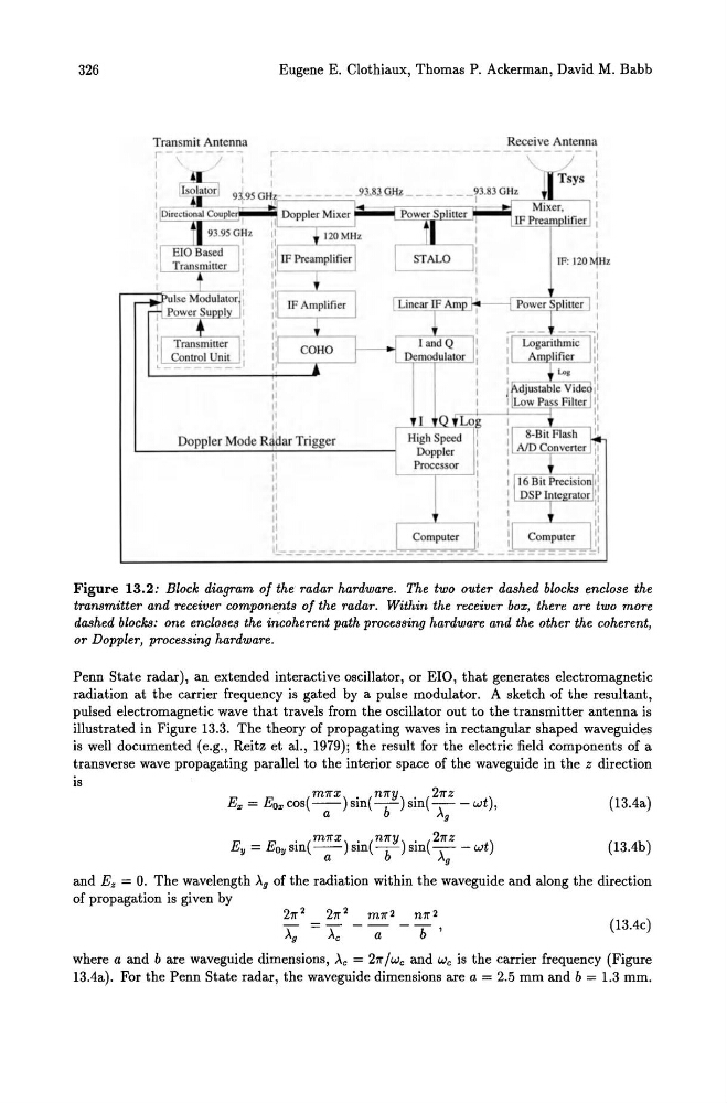
Figure 13.2: Block diagram of the radar hardware. The two outer dashed blocks enclose the
transmitter and receiver components of the radar. Within the receiver box, there are two more
dashed blocks: one encloses the incoherent path processing hardware and the other the coherent,
or Doppler, processing hardware.
Penn State radar), an extended interactive oscillator, or EIO, that generates electromagnetic
radiation at the carrier frequency is gated by a pulse modulator. A sketch of the resultant,
pulsed electromagnetic wave that travels from the oscillator out to the transmitter antenna is
illustrated in Figure 13.3. The theory of propagating waves in rectangular shaped waveguides
is well documented (e.g., Reitz et aI., 1979); the result for the electric field components of a
transverse wave propagating parallel to the interior space of the waveguide in the z direction
is
m7rX . n7ry . 27r Z
Ex = Eox cos(-a-) sm(-b-) sm( A; - wt),
E
E . (m7rx) . (n7rY) . (27rz
)
y = Oysm -a- sm -b- sm A; -wt
(13.4a)
(13.4b)
and Ez = o. The wavelength )..g of the radiation within the waveguide and along the direction
of propagation is given by
27r 2
27r 2 m7r 2 n7r 2
)..g
)..e - -;:; - b '
(13.4c)
where a and b are waveguide dimensions, )..e = 27r / We and We is the carrier frequency (Figure
13.4a). For the Penn State radar, the waveguide dimensions are a = 2.5 mm and b = 1.3 mm.
Eugene E. Clothiaux, Thomas P. Ackerman, David M. Babb
Receive Antenna
r-------------------------------l
I
I
I
I
I
~~~~~~~~~~~~~~~~~==~~~~I: I
'-=--'-'-'''T-'-''="",-, I
I
I
Figure 13.2: Block diagram of the radar hardware. The two outer dashed blocks enclose the
transmitter and receiver components of the radar. Within the receiver box, there are two more
dashed blocks: one encloses the incoherent path processing hardware and the other the coherent,
or Doppler, processing hardware.
Penn State radar), an extended interactive oscillator, or EIO, that generates electromagnetic
radiation at the carrier frequency is gated by a pulse modulator. A sketch of the resultant,
pulsed electromagnetic wave that travels from the oscillator out to the transmitter antenna is
illustrated in Figure 13.3. The theory of propagating waves in rectangular shaped waveguides
is well documented (e.g., Reitz et aI., 1979); the result for the electric field components of a
transverse wave propagating parallel to the interior space of the waveguide in the z direction
is
m7rX . n7ry . 27r Z
Ex = Eox cos(-a-) sm(-b-) sm( A; - wt),
E
E . (m7rx) . (n7rY) . (27rz
)
y = Oysm -a- sm -b- sm A; -wt
(13.4a)
(13.4b)
and Ez = o. The wavelength )..g of the radiation within the waveguide and along the direction
of propagation is given by
27r 2
27r 2 m7r 2 n7r 2
)..g
)..e - -;:; - b '
(13.4c)
where a and b are waveguide dimensions, )..e = 27r / We and We is the carrier frequency (Figure
13.4a). For the Penn State radar, the waveguide dimensions are a = 2.5 mm and b = 1.3 mm.