

Ground-Based Remote Sensing of Cloud Properties ...
325
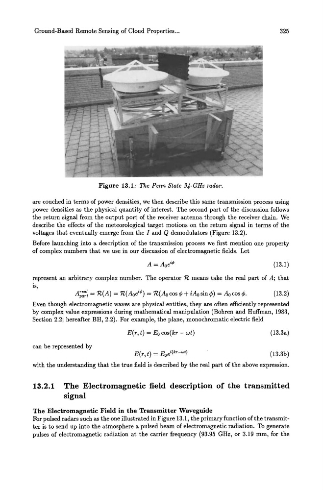
Figure 13.1: The Penn State 94-GHz radar.
are couched in terms of power densities, we then describe this same transmission process using
power densities as the physical quantity of interest. The second part of the discussion follows
the return signal from the output port of the receiver antenna through the receiver chain. We
describe the effects of the meteorological target motions on the return signal in terms of the
voltages that eventually emerge from the I and Q demodulators (Figure 13.2).
Before launching into a description of the transmission process we first mention one property
of complex numbers that we use in our discussion of electromagnetic fields. Let
(13.1)
represent an arbitrary complex number. The operator R means take the real part of A; that
is,
A;:~~ = R(A) = R(Aoei
Even though electromagnetic waves are physical entities, they are often efficiently represented
by complex value expressions during mathematical manipulation (Bohren and Huffman, 1983,
Section 2.2; hereafter BH, 2.2). For example, the plane, monochromatic electric field
E(r, t) = Eo cos(kr - wt)
(13.3a)
can be represented by
E(r, t) = Eoei(kr-wt)
(13.3b)
with the understanding that the true field is described by the real part of the above expression.
13.2.1 The Electromagnetic field description of the transmitted
signal
The Electromagnetic Field in the Transmitter Waveguide
For pulsed radars such as the one illustrated in Figure 13.1, the primary function of the transmitter is to send up into the atmosphere a pulsed beam of electromagnetic radiation. To generate
pulses of electromagnetic radiation at the carrier frequency (93.95 GHz, or 3.19 mm, for the
325
Figure 13.1: The Penn State 94-GHz radar.
are couched in terms of power densities, we then describe this same transmission process using
power densities as the physical quantity of interest. The second part of the discussion follows
the return signal from the output port of the receiver antenna through the receiver chain. We
describe the effects of the meteorological target motions on the return signal in terms of the
voltages that eventually emerge from the I and Q demodulators (Figure 13.2).
Before launching into a description of the transmission process we first mention one property
of complex numbers that we use in our discussion of electromagnetic fields. Let
(13.1)
represent an arbitrary complex number. The operator R means take the real part of A; that
is,
A;:~~ = R(A) = R(Aoei
Even though electromagnetic waves are physical entities, they are often efficiently represented
by complex value expressions during mathematical manipulation (Bohren and Huffman, 1983,
Section 2.2; hereafter BH, 2.2). For example, the plane, monochromatic electric field
E(r, t) = Eo cos(kr - wt)
(13.3a)
can be represented by
E(r, t) = Eoei(kr-wt)
(13.3b)
with the understanding that the true field is described by the real part of the above expression.
13.2.1 The Electromagnetic field description of the transmitted
signal
The Electromagnetic Field in the Transmitter Waveguide
For pulsed radars such as the one illustrated in Figure 13.1, the primary function of the transmitter is to send up into the atmosphere a pulsed beam of electromagnetic radiation. To generate
pulses of electromagnetic radiation at the carrier frequency (93.95 GHz, or 3.19 mm, for the