

Precipitation at the Ground: Radar Techniques
307
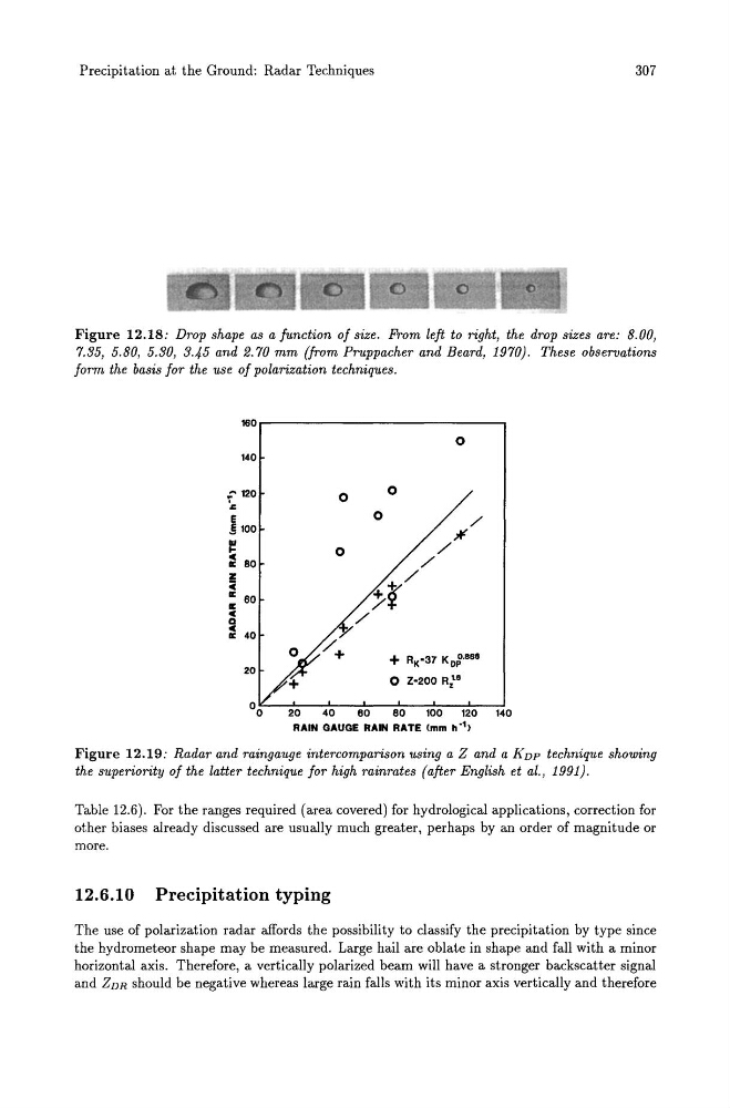
Figure 12.18: Drop shape as a function of size. From left to right, the drop sizes are: 8.00,
7.35, 5.80, 5.30, 3.45 and 2.70 mm (from Pruppacher and Beard, 1970). These observations
form the basis for the use of polarization techniques.
160
140
:- 120
.,
E
.§ 100
.. l- e BO
II:
! II:
II:
60
e Q
e 40
II:
20
o
o
o
o
o
+ R K '37 KD~··B.
o Z'200 Ri"
40
60
eo 100 120 140
RAIN GAUGE RAIN RATE (mm ho1)
Figure 12.19: Radar and raingauge intercomparison using a Z and a K DP technique showing
the superiority of the latter technique for high rainrates (after English et al., 1991).
Table 12.6). For the ranges required (area covered) for hydrological applications, correction for
other biases already discussed are usually much greater, perhaps by an order of magnitude or
more.
12.6.10 Precipitation typing
The use of polarization radar affords the possibility to classify the precipitation by type since
the hydrometeor shape may be measured. Large hail are oblate in shape and fall with a minor
horizontal axis. Therefore, a vertically polarized beam will have a stronger backscatter signal
and ZDR should be negative whereas large rain falls with its minor axis vertically and therefore
307
Figure 12.18: Drop shape as a function of size. From left to right, the drop sizes are: 8.00,
7.35, 5.80, 5.30, 3.45 and 2.70 mm (from Pruppacher and Beard, 1970). These observations
form the basis for the use of polarization techniques.
160
140
:- 120
.,
E
.§ 100
.. l- e BO
II:
! II:
II:
60
e Q
e 40
II:
20
o
o
o
o
o
+ R K '37 KD~··B.
o Z'200 Ri"
40
60
eo 100 120 140
RAIN GAUGE RAIN RATE (mm ho1)
Figure 12.19: Radar and raingauge intercomparison using a Z and a K DP technique showing
the superiority of the latter technique for high rainrates (after English et al., 1991).
Table 12.6). For the ranges required (area covered) for hydrological applications, correction for
other biases already discussed are usually much greater, perhaps by an order of magnitude or
more.
12.6.10 Precipitation typing
The use of polarization radar affords the possibility to classify the precipitation by type since
the hydrometeor shape may be measured. Large hail are oblate in shape and fall with a minor
horizontal axis. Therefore, a vertically polarized beam will have a stronger backscatter signal
and ZDR should be negative whereas large rain falls with its minor axis vertically and therefore