

11.2 Grid quality and optimization
343
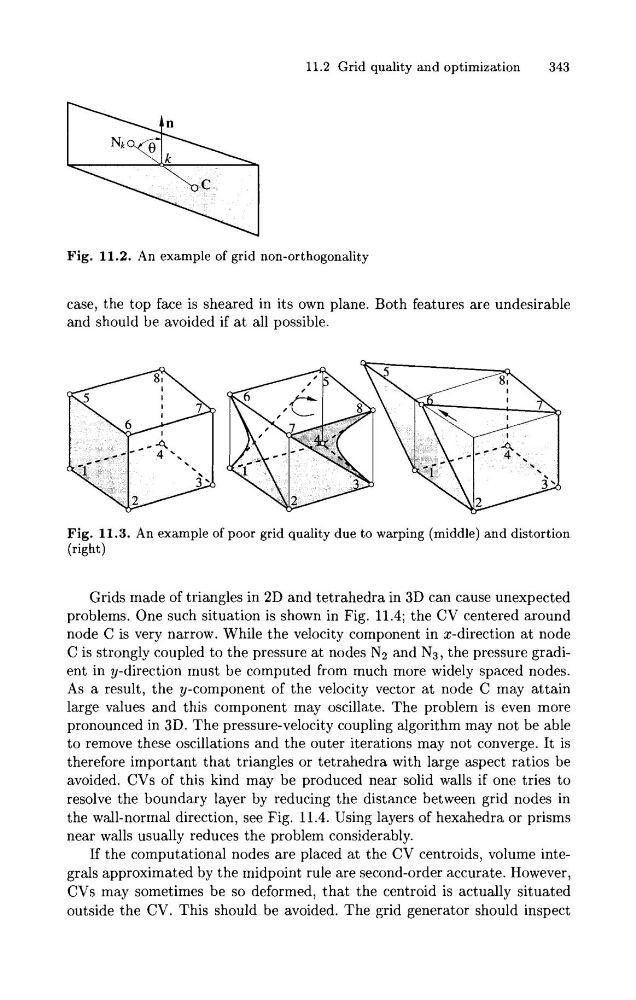
Fig. 11.2. An example of grid non-orthogonality
case, the top face is sheared in its own plane. Both features are undesirable
and should be avoided if a t all possible.
Fig. 11.3. An example of poor grid quality due to warping (middle) and distortion
(right)
Grids made of triangles in 2D and tetrahedra in 3D can cause unexpected
problems. One such situation is shown in Fig. 11.4; the CV centered around
node C is very narrow. While the velocity component in x-direction at node
C is strongly coupled to the pressure at nodes N2 and N3, the pressure gradient in y-direction must be computed from much more widely spaced nodes.
As a result, the y-component of the velocity vector at node C may attain
large values and this component may oscillate. The problem is even more
pronounced in 3D. The pressure-velocity coupling algorithm may not be able
to remove these oscillations and the outer iterations may not converge. It is
therefore important that triangles or tetrahedra with large aspect ratios be
avoided. CVs of this kind may be produced near solid walls if one tries to
resolve the boundary layer by reducing the distance between grid nodes in
the wall-normal direction, see Fig. 11.4. Using layers of hexahedra or prisms
near walls usually reduces the problem considerably.
If the computational nodes are placed at the CV centroids, volume integrals approximated by the midpoint rule are second-order accurate. However,
CVs may sometimes be so deformed, that the centroid is actually situated
outside the CV. This should be avoided. The grid generator should inspect
343
Fig. 11.2. An example of grid non-orthogonality
case, the top face is sheared in its own plane. Both features are undesirable
and should be avoided if a t all possible.
Fig. 11.3. An example of poor grid quality due to warping (middle) and distortion
(right)
Grids made of triangles in 2D and tetrahedra in 3D can cause unexpected
problems. One such situation is shown in Fig. 11.4; the CV centered around
node C is very narrow. While the velocity component in x-direction at node
C is strongly coupled to the pressure at nodes N2 and N3, the pressure gradient in y-direction must be computed from much more widely spaced nodes.
As a result, the y-component of the velocity vector at node C may attain
large values and this component may oscillate. The problem is even more
pronounced in 3D. The pressure-velocity coupling algorithm may not be able
to remove these oscillations and the outer iterations may not converge. It is
therefore important that triangles or tetrahedra with large aspect ratios be
avoided. CVs of this kind may be produced near solid walls if one tries to
resolve the boundary layer by reducing the distance between grid nodes in
the wall-normal direction, see Fig. 11.4. Using layers of hexahedra or prisms
near walls usually reduces the problem considerably.
If the computational nodes are placed at the CV centroids, volume integrals approximated by the midpoint rule are second-order accurate. However,
CVs may sometimes be so deformed, that the centroid is actually situated
outside the CV. This should be avoided. The grid generator should inspect