

304
9. Turbulent Flows
Similar conclusions were drawn by Bertram and Jansen (1994), who used a
commercial CFD code employing the k-E turbulence model and wall functions
to calculate drag of three variants of a ship hull model. They found that the
computed drag coefficient was low by about 12% in absolute value; however,
the relative increase or reduction of the drag when the geometry was changed
was predicted with the accuracy of about 2%. The best hull form from the
numerical study was also the best in the towing tank.
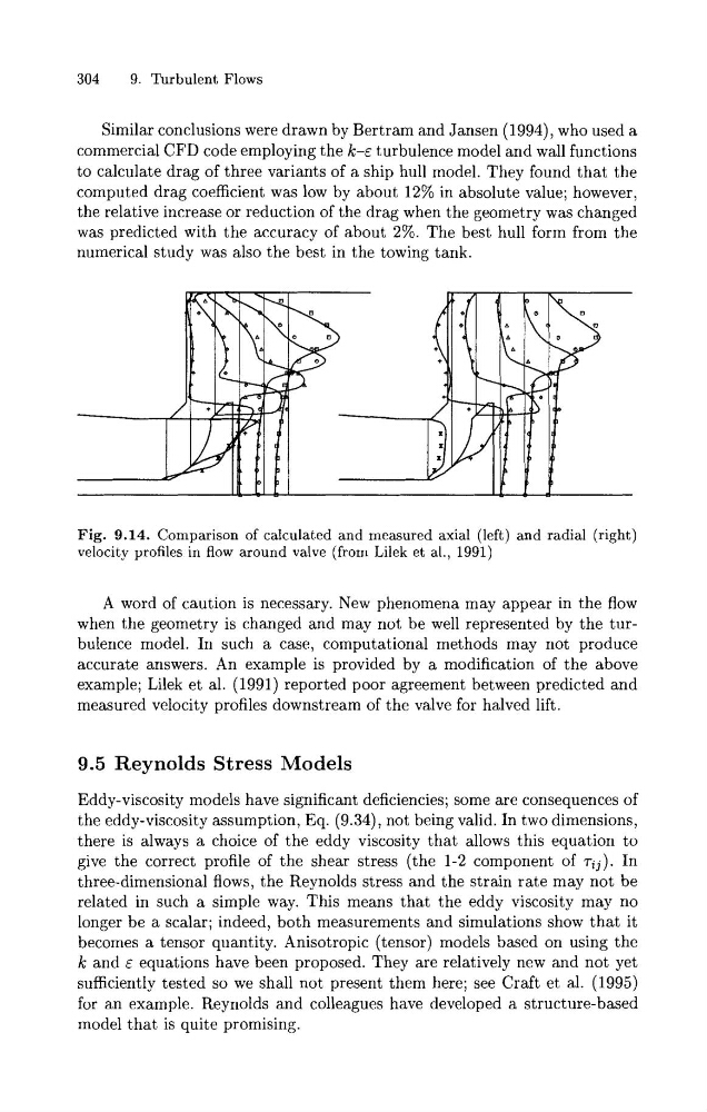
Fig. 9.14. Comparison of calculated and measured axial (left) and radial (right)
velocity profiles in flow around valve (from Lilek et al., 1991)
A word of caution is necessary. New phenomena may appear in the flow
when the geometry is changed and may not be well represented by the turbulence model. In such a case, computational methods may not produce
accurate answers. An example is provided by a modification of the above
example; Lilek et al. (1991) reported poor agreement between predicted and
measured velocity profiles downstream of the valve for halved lift.
9.5 Reynolds Stress Models
Eddy-viscosity models have significant deficiencies; some are consequences of
the eddy-viscosity assumption, Eq. (9.34), not being valid. In two dimensions,
there is always a choice of the eddy viscosity that allows this equation to
give the correct profile of the shear stress (the 1-2 component of r i j ) . In
three-dimensional flows, the Reynolds stress and the strain rate may not be
related in such a simple way. This means that the eddy viscosity may no
longer be a scalar; indeed, both measurements and simulations show that it
becomes a tensor quantity. Anisotropic (tensor) models based on using the
k and E equations have been proposed. They are relatively new and not yet
sufficiently tested so we shall not present them here; see Craft et al. (1995)
for an example. Reynolds and colleagues have developed a structure-based
model that is quite promising.
9. Turbulent Flows
Similar conclusions were drawn by Bertram and Jansen (1994), who used a
commercial CFD code employing the k-E turbulence model and wall functions
to calculate drag of three variants of a ship hull model. They found that the
computed drag coefficient was low by about 12% in absolute value; however,
the relative increase or reduction of the drag when the geometry was changed
was predicted with the accuracy of about 2%. The best hull form from the
numerical study was also the best in the towing tank.
Fig. 9.14. Comparison of calculated and measured axial (left) and radial (right)
velocity profiles in flow around valve (from Lilek et al., 1991)
A word of caution is necessary. New phenomena may appear in the flow
when the geometry is changed and may not be well represented by the turbulence model. In such a case, computational methods may not produce
accurate answers. An example is provided by a modification of the above
example; Lilek et al. (1991) reported poor agreement between predicted and
measured velocity profiles downstream of the valve for halved lift.
9.5 Reynolds Stress Models
Eddy-viscosity models have significant deficiencies; some are consequences of
the eddy-viscosity assumption, Eq. (9.34), not being valid. In two dimensions,
there is always a choice of the eddy viscosity that allows this equation to
give the correct profile of the shear stress (the 1-2 component of r i j ) . In
three-dimensional flows, the Reynolds stress and the strain rate may not be
related in such a simple way. This means that the eddy viscosity may no
longer be a scalar; indeed, both measurements and simulations show that it
becomes a tensor quantity. Anisotropic (tensor) models based on using the
k and E equations have been proposed. They are relatively new and not yet
sufficiently tested so we shall not present them here; see Craft et al. (1995)
for an example. Reynolds and colleagues have developed a structure-based
model that is quite promising.