

286
9. Turbulent Flows
Figure 9.5 gives the streamlines of the time-averaged flow in the region
close to the wall; a great deal of information about the flow can be discerned
from this plot. The incoming flow does not separate in the traditional sense
but reaches a stagnation or saddle point (marked by A on the figure) and
goes around the body. Some of the flow further above the lower wall hits the
front face of the cube; about half of it flows downwards and creates the region
of reversed flow in front of the body. As the flow down the front face of the
cube nears the lower wall, there is a secondary separation and a reattachment
line (marked by B in the figure) just ahead of the cube. On each side of the
cube, one finds a region of converging streamlines (marked as C) and another
of diverging streamlines (marked D); these are the traces of the horseshoe
vortex (about which more is said below). Behind the body one finds two
areas of swirling flow (marked E) which are the footprints of an arch vortex.
Finally, there is a reattachment line (marked H) further downstream of the
body.
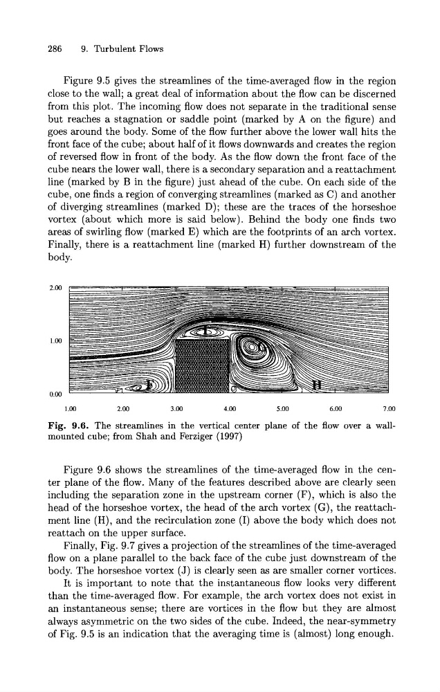
Fig. 9.6. The streamlines in the vertical center plane of the flow over a wallmounted cube; from Shah and Ferziger (1997)
Figure 9.6 shows the streamlines of the time-averaged flow in the center plane of the flow. Many of the features described above are clearly seen
including the separation zone in the upstream corner (F), which is also the
head of the horseshoe vortex, the head of the arch vortex (G), the reattachment line (H), and the recirculation zone (I) above the body which does not
reattach on the upper surface.
Finally, Fig. 9.7 gives a projection of the streamlines of the time-averaged
flow on a plane parallel to the back face of the cube just downstream of the
body. The horseshoe vortex (J) is clearly seen as are smaller corner vortices.
It is important to note that the instantaneous flow looks very different
than the time-averaged flow. For example, the arch vortex does not exist in
an instantaneous sense; there are vortices in the flow but they are almost
always asymmetric on the two sides of the cube. Indeed, the near-symmetry
of Fig. 9.5 is an indication that the averaging time is (almost) long enough.
9. Turbulent Flows
Figure 9.5 gives the streamlines of the time-averaged flow in the region
close to the wall; a great deal of information about the flow can be discerned
from this plot. The incoming flow does not separate in the traditional sense
but reaches a stagnation or saddle point (marked by A on the figure) and
goes around the body. Some of the flow further above the lower wall hits the
front face of the cube; about half of it flows downwards and creates the region
of reversed flow in front of the body. As the flow down the front face of the
cube nears the lower wall, there is a secondary separation and a reattachment
line (marked by B in the figure) just ahead of the cube. On each side of the
cube, one finds a region of converging streamlines (marked as C) and another
of diverging streamlines (marked D); these are the traces of the horseshoe
vortex (about which more is said below). Behind the body one finds two
areas of swirling flow (marked E) which are the footprints of an arch vortex.
Finally, there is a reattachment line (marked H) further downstream of the
body.
Fig. 9.6. The streamlines in the vertical center plane of the flow over a wallmounted cube; from Shah and Ferziger (1997)
Figure 9.6 shows the streamlines of the time-averaged flow in the center plane of the flow. Many of the features described above are clearly seen
including the separation zone in the upstream corner (F), which is also the
head of the horseshoe vortex, the head of the arch vortex (G), the reattachment line (H), and the recirculation zone (I) above the body which does not
reattach on the upper surface.
Finally, Fig. 9.7 gives a projection of the streamlines of the time-averaged
flow on a plane parallel to the back face of the cube just downstream of the
body. The horseshoe vortex (J) is clearly seen as are smaller corner vortices.
It is important to note that the instantaneous flow looks very different
than the time-averaged flow. For example, the arch vortex does not exist in
an instantaneous sense; there are vortices in the flow but they are almost
always asymmetric on the two sides of the cube. Indeed, the near-symmetry
of Fig. 9.5 is an indication that the averaging time is (almost) long enough.