

310
p...
U
0
<
S 0
c.I::
0.0
r:::
~
9 Experimental Methods in Fluid Mechanics
5
4
3
2
O~L---Y-~i-~~~~~~--------~
~
' !\,C1
<;
transmit
pulse
Time
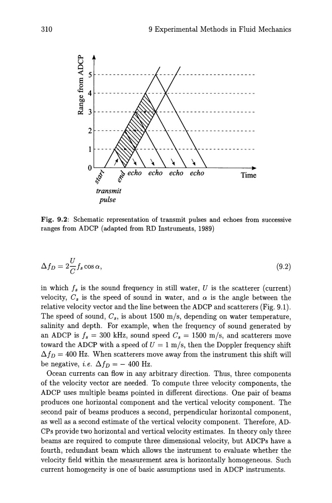
Fig. 9.2: Schematic representation of transmit pulses and echoes from successive
ranges from ADCP (adapted from RD Instruments, 1989)
(9.2)
in which Is is the sound frequency in still water, U is the scatterer (current)
velocity, Cs is the speed of sound in water, and 0: is the angle between the
relative velocity vector and the line between the ADCP and scatterers (Fig. 9.1).
The speed of sound, Cs, is about 1500 mis, depending on water temperature,
salinity and depth. For example, when the frequency of sound generated by
an ADCP is Is = 300 kHz, sound speed Cs = 1500 mis, and scatterers move
toward the ADCP with a speed of U = 1 mis, then the Doppler frequency shift
6.1 D = 400 Hz. When scatterers move away from the instrument this shift will
be negative, i.e. 6.ID = - 400 Hz.
Ocean currents can flow in any arbitrary direction. Thus, three components
of the velocity vector are needed. To compute three velocity components, the
ADCP uses multiple beams pointed in different directions. One pair of beams
produces one horizontal component and the vertical velocity component. The
second pair of beams produces a second, perpendicular horizontal component,
as well as a second estimate of the vertical velocity component. Therefore, ADCPs provide two horizontal and vertical velocity estimates. In theory only three
beams are required to compute three dimensional velocity, but ADCPs have a
fourth, redundant beam which allows the instrument to evaluate whether the
velocity field within the measurement area is horizontally homogeneous. Such
current homogeneity is one of basic assumptions used in ADCP instruments.
p...
U
0
<
S 0
c.I::
0.0
r:::
~
9 Experimental Methods in Fluid Mechanics
5
4
3
2
O~L---Y-~i-~~~~~~--------~
~
' !\,C1
<;
transmit
pulse
Time
Fig. 9.2: Schematic representation of transmit pulses and echoes from successive
ranges from ADCP (adapted from RD Instruments, 1989)
(9.2)
in which Is is the sound frequency in still water, U is the scatterer (current)
velocity, Cs is the speed of sound in water, and 0: is the angle between the
relative velocity vector and the line between the ADCP and scatterers (Fig. 9.1).
The speed of sound, Cs, is about 1500 mis, depending on water temperature,
salinity and depth. For example, when the frequency of sound generated by
an ADCP is Is = 300 kHz, sound speed Cs = 1500 mis, and scatterers move
toward the ADCP with a speed of U = 1 mis, then the Doppler frequency shift
6.1 D = 400 Hz. When scatterers move away from the instrument this shift will
be negative, i.e. 6.ID = - 400 Hz.
Ocean currents can flow in any arbitrary direction. Thus, three components
of the velocity vector are needed. To compute three velocity components, the
ADCP uses multiple beams pointed in different directions. One pair of beams
produces one horizontal component and the vertical velocity component. The
second pair of beams produces a second, perpendicular horizontal component,
as well as a second estimate of the vertical velocity component. Therefore, ADCPs provide two horizontal and vertical velocity estimates. In theory only three
beams are required to compute three dimensional velocity, but ADCPs have a
fourth, redundant beam which allows the instrument to evaluate whether the
velocity field within the measurement area is horizontally homogeneous. Such
current homogeneity is one of basic assumptions used in ADCP instruments.