

418
8. Nonreflecting Boundary Conditions
Irl
o
30
Angle of Incidencc
60
90
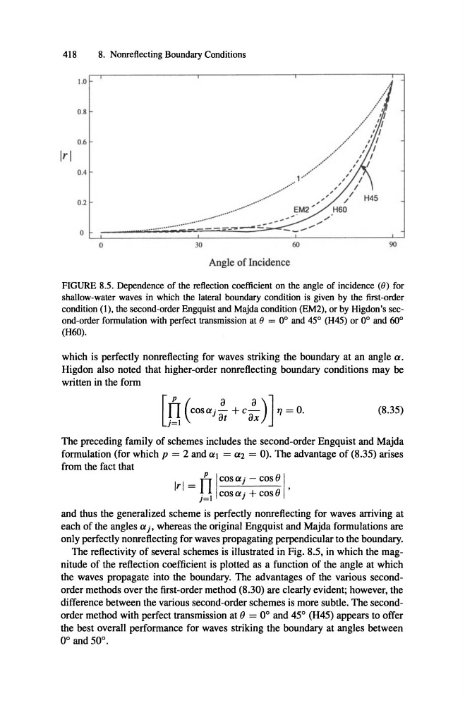
FIGURE 8.5. Dependence of the reflection coefficient on the angle of incidence (9) for
shallow-water waves in which the lateral boundary condition is given by the first-order
condition (1), the second-order Engquist and Majdacondition(EM2), or by Higdon's second-orderfonnulation with perfect transmission at 9 = 0° and 45° (H45) or 0° and 60°
(H60).
which is perfectly nonreflecting for waves striking the boundary at an angle a,
Higdon also noted that higher-order nonreflecting boundary conditions may be
written in the form
[ fI
+
17 = o.
(8.35)
j=1
at ax
The preceding family of schemes includes the second-order Engquist and Majda
formulation (for which p = 2 and ctl = ct2 = 0). The advantage of (8.35) arises
from the fact that
IrJ = fl
p Icos a j - cos oI
j=1 COSa j + cos ()
,
and thus the generalized scheme is perfectly nonreflecting for waves arriving at
each of the angles a j, whereas the original Engquist and Majda formulations are
only perfectly nonreflecting for waves propagating perpendicular to the boundary.
The reflectivity of several schemes is illustrated in Fig. 8.5, in which the magnitude of the reflection coefficient is plotted as a function of the angle at which
the waves propagate into the boundary. The advantages of the various secondorder methods over the first-order method (8.30) are c1early evident; however, the
difference between the various second-order schemes is more subtle . The secondorder method with perfect transmission at () = 0° and 45° (H45) appears to offer
the best overall performance for waves striking the boundary at angles between
0° and 50°.
8. Nonreflecting Boundary Conditions
Irl
o
30
Angle of Incidencc
60
90
FIGURE 8.5. Dependence of the reflection coefficient on the angle of incidence (9) for
shallow-water waves in which the lateral boundary condition is given by the first-order
condition (1), the second-order Engquist and Majdacondition(EM2), or by Higdon's second-orderfonnulation with perfect transmission at 9 = 0° and 45° (H45) or 0° and 60°
(H60).
which is perfectly nonreflecting for waves striking the boundary at an angle a,
Higdon also noted that higher-order nonreflecting boundary conditions may be
written in the form
[ fI
+
17 = o.
(8.35)
j=1
at ax
The preceding family of schemes includes the second-order Engquist and Majda
formulation (for which p = 2 and ctl = ct2 = 0). The advantage of (8.35) arises
from the fact that
IrJ = fl
p Icos a j - cos oI
j=1 COSa j + cos ()
,
and thus the generalized scheme is perfectly nonreflecting for waves arriving at
each of the angles a j, whereas the original Engquist and Majda formulations are
only perfectly nonreflecting for waves propagating perpendicular to the boundary.
The reflectivity of several schemes is illustrated in Fig. 8.5, in which the magnitude of the reflection coefficient is plotted as a function of the angle at which
the waves propagate into the boundary. The advantages of the various secondorder methods over the first-order method (8.30) are c1early evident; however, the
difference between the various second-order schemes is more subtle . The secondorder method with perfect transmission at () = 0° and 45° (H45) appears to offer
the best overall performance for waves striking the boundary at angles between
0° and 50°.