

416
8. Nonreflecting Boundary Conditions
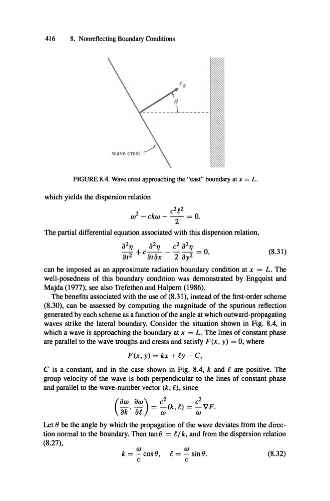
FIGURE 8.4. Wave crest approaching the "east" boundary at x = L.
which yields the dispersion relation
c
2 l
2
w 2 - ckto - - - = o.
2
The partial differential equation associated with this dispersion relation,
;PTJ
-
8t 2
;PTJ c 2 8271
+c- - - - = 0,
8t8x
2 8y2
(8.31)
can be imposed as an approximate radiation boundary condition at x = L. The
well-posedness of this boundary condition was demonstrated by Engquist and
Majda (1977); see also Trefethen and Halpem (1986).
The benefits associated with the use of (8.31), instead of the first-order scheme
(8.30), can be assessed by computing the magnitude of the spurious reflection
generated by each scheme as a function of the angle at which outward-propagating
waves strike the lateral boundary. Consider the situation shown in Fig. 8.4, in
which a wave is approaching the boundary at x = L. The lines of constant phase
are parallel to the wave troughs and crests and satisfy F (x, y) = 0, where
F(x , y) = kx + ly - C,
C is a constant, and in the case shown in Fig. 8.4, k and l are positive. The
group velocity of the wave is both perpendicular to the lines of constant phase
and parallel to the wave-number vector (k, l), since
2
2
- , -
8W 8W) = c
-(k,l) = c
-VF.
( 8k 8l
co
tu
Let () be the angle by which the propagation of the wave deviates from the direction normal to the boundary. Then tan() = ljk, and from the dispersion relation
(8.27),
w
k = - cos ä,
c
(8.32)
w.
l = - sin s.
c
8. Nonreflecting Boundary Conditions
FIGURE 8.4. Wave crest approaching the "east" boundary at x = L.
which yields the dispersion relation
c
2 l
2
w 2 - ckto - - - = o.
2
The partial differential equation associated with this dispersion relation,
;PTJ
-
8t 2
;PTJ c 2 8271
+c- - - - = 0,
8t8x
2 8y2
(8.31)
can be imposed as an approximate radiation boundary condition at x = L. The
well-posedness of this boundary condition was demonstrated by Engquist and
Majda (1977); see also Trefethen and Halpem (1986).
The benefits associated with the use of (8.31), instead of the first-order scheme
(8.30), can be assessed by computing the magnitude of the spurious reflection
generated by each scheme as a function of the angle at which outward-propagating
waves strike the lateral boundary. Consider the situation shown in Fig. 8.4, in
which a wave is approaching the boundary at x = L. The lines of constant phase
are parallel to the wave troughs and crests and satisfy F (x, y) = 0, where
F(x , y) = kx + ly - C,
C is a constant, and in the case shown in Fig. 8.4, k and l are positive. The
group velocity of the wave is both perpendicular to the lines of constant phase
and parallel to the wave-number vector (k, l), since
2
2
- , -
8W 8W) = c
-(k,l) = c
-VF.
( 8k 8l
co
tu
Let () be the angle by which the propagation of the wave deviates from the direction normal to the boundary. Then tan() = ljk, and from the dispersion relation
(8.27),
w
k = - cos ä,
c
(8.32)
w.
l = - sin s.
c