

3.5 Implementation standards
121
Node
Node
Node
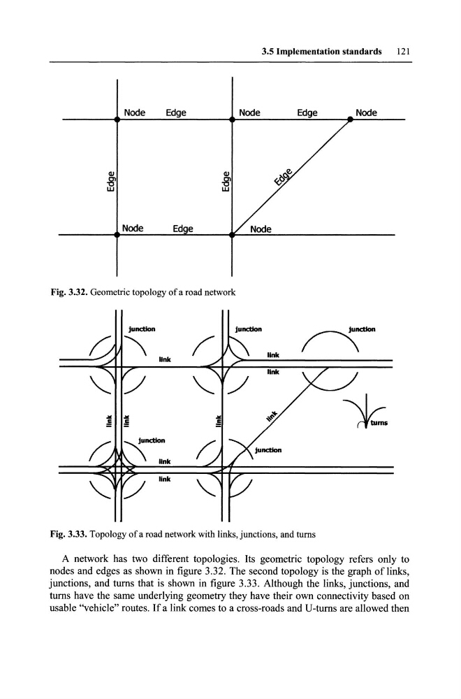
Fig. 3.32. Geometrie topology of a road network
link
Fig. 3.33. Topology of a road network with links, junctions, and turns
A network has two different topologies. Its geometrie topology refers only to
nodes and edges as shown in figure 3.32. The second topology is the graph of links,
junctions, and turns that is shown in figure 3.33. Although the links, junctions, and
turns have the same underlying geometry they have their own connectivity based on
usable "vehicle" routes. If a link comes to a cross-roads and U-turns are allowed then
121
Node
Node
Node
Fig. 3.32. Geometrie topology of a road network
link
Fig. 3.33. Topology of a road network with links, junctions, and turns
A network has two different topologies. Its geometrie topology refers only to
nodes and edges as shown in figure 3.32. The second topology is the graph of links,
junctions, and turns that is shown in figure 3.33. Although the links, junctions, and
turns have the same underlying geometry they have their own connectivity based on
usable "vehicle" routes. If a link comes to a cross-roads and U-turns are allowed then