

272
Air Pollution and Turbulence: Modeling and Applications
allow the implementation of “integrated” physical and chemical parameterization
schemes.
Moreover, it is also advisable to simulate all the chemical reactions that take place
between ozone precursors, namely, NO x and VOCs. However, an explicit treatment
of all these reactions is practically impossible and, for most purposes, the numerical
simulations use a condensed kinetic mechanism to avoid excessive numerical costs
which means that the chemical scheme is often simplifi ed down to a small number of
chemical reactions (Aumont et al., 1997). Therefore, a critical component of a CTM
is the chemical mechanism that describes how VOCs and NO x interact to produce
ozone and other oxidants. The daily maximum ozone concentrations generated in
mixtures with various initial VOC and NO x concentrations can be represented by an
isopleth diagram using a method called the ozone isopleth plotting method, and can
then be used for the assessment of O 3 control strategies. Figure 10.3 gives an example
of a set of typical O 3 isopleths. In Figure 10.3, point A represents a base case O 3 concentration and point B represents a control case O 3 concentration as simulated by the
OZIPM/EKMA model. In this case, for example, to attain an O 3 level of 0.12 ppm
(point B), VOCs need to be reduced from 0.9 ppm (point A) to 0.3 ppm (point B)
assuming that NO x remains the same. The OZIPM/EKMA model was widely used
in the 1970s and 1980s for O 3 control strategy assessment before high-performance
computer platforms become available.
Hence, chemical mechanisms were fi rst used in models more than 20 years ago.
Since then, there has been an enormous growth in our understanding of the chemical
processes that lead to oxidant production, especially in that area concerning the role
of organic species.
Nowadays, there are several chemical mechanisms included in several different
CTMs. The carbon bond mechanism version 4 (CB-IV), the SAPRC99 (Statewide
Air Pollution Research Center 99), the KOREM, and the EMEP (cooperative program for monitoring and evaluation of the long-range transmission of air pollutants
Meteorology
Topography
Emissions
Air quality
Landuse
Meteorological
model
Chemical
model
3D and 2D meteorological
fields (temp, wind, water
vapour, precipitation,...)
3D pollutant
concentration
fields
2D pollutant
deposition
fields
Models
Results
Input data
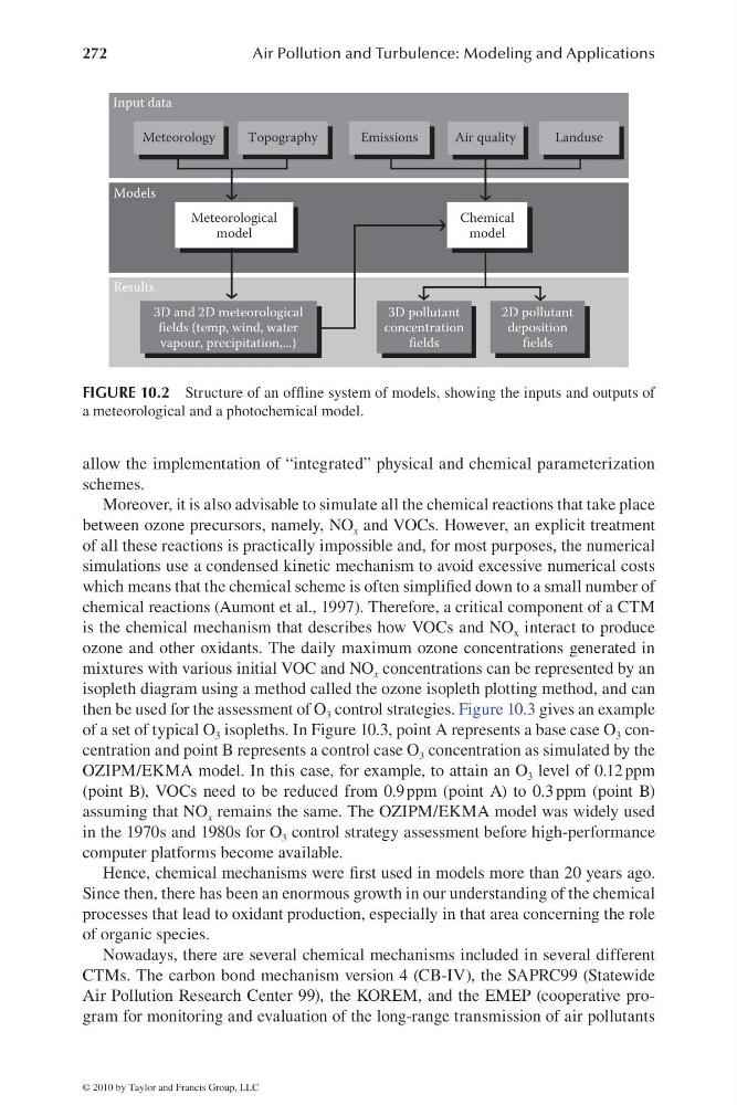
FIGURE 10.2 Structure of an offl ine system of models, showing the inputs and outputs of
a meteorological and a photochemical model.
© 2010 by Taylor and Francis Group, LLC
Air Pollution and Turbulence: Modeling and Applications
allow the implementation of “integrated” physical and chemical parameterization
schemes.
Moreover, it is also advisable to simulate all the chemical reactions that take place
between ozone precursors, namely, NO x and VOCs. However, an explicit treatment
of all these reactions is practically impossible and, for most purposes, the numerical
simulations use a condensed kinetic mechanism to avoid excessive numerical costs
which means that the chemical scheme is often simplifi ed down to a small number of
chemical reactions (Aumont et al., 1997). Therefore, a critical component of a CTM
is the chemical mechanism that describes how VOCs and NO x interact to produce
ozone and other oxidants. The daily maximum ozone concentrations generated in
mixtures with various initial VOC and NO x concentrations can be represented by an
isopleth diagram using a method called the ozone isopleth plotting method, and can
then be used for the assessment of O 3 control strategies. Figure 10.3 gives an example
of a set of typical O 3 isopleths. In Figure 10.3, point A represents a base case O 3 concentration and point B represents a control case O 3 concentration as simulated by the
OZIPM/EKMA model. In this case, for example, to attain an O 3 level of 0.12 ppm
(point B), VOCs need to be reduced from 0.9 ppm (point A) to 0.3 ppm (point B)
assuming that NO x remains the same. The OZIPM/EKMA model was widely used
in the 1970s and 1980s for O 3 control strategy assessment before high-performance
computer platforms become available.
Hence, chemical mechanisms were fi rst used in models more than 20 years ago.
Since then, there has been an enormous growth in our understanding of the chemical
processes that lead to oxidant production, especially in that area concerning the role
of organic species.
Nowadays, there are several chemical mechanisms included in several different
CTMs. The carbon bond mechanism version 4 (CB-IV), the SAPRC99 (Statewide
Air Pollution Research Center 99), the KOREM, and the EMEP (cooperative program for monitoring and evaluation of the long-range transmission of air pollutants
Meteorology
Topography
Emissions
Air quality
Landuse
Meteorological
model
Chemical
model
3D and 2D meteorological
fields (temp, wind, water
vapour, precipitation,...)
3D pollutant
concentration
fields
2D pollutant
deposition
fields
Models
Results
Input data
FIGURE 10.2 Structure of an offl ine system of models, showing the inputs and outputs of
a meteorological and a photochemical model.
© 2010 by Taylor and Francis Group, LLC