

264
T. Sueishi and W. Yoshikoshi
aerated zone. The practical example of analysis using Eq. (7) will be shown in the next
section.
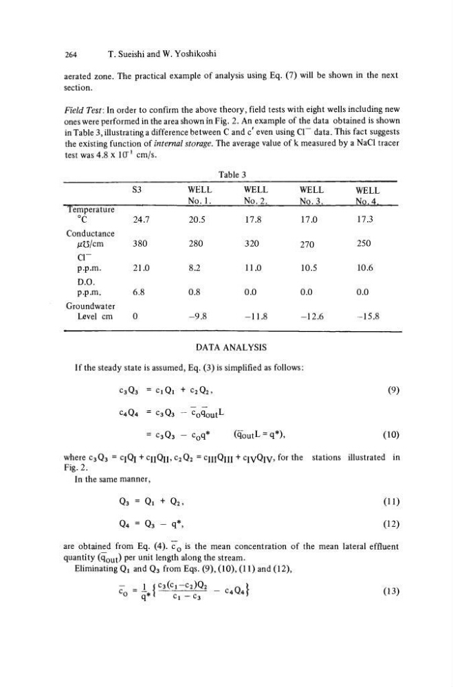
Field Test: In order to confirm the above theory, field tests with eight wells including new
ones were performed in the area shown in Fig. 2. An example of the data obtained is shown
in Table 3, illustrating a difference between C and c' even using Cl~ data. This fact suggests
the existing function of internal storage. The average value of k measured by a NaCl tracer
test was 4.8 x 1CT
1 cm/s.
Table 3
Temperature
°C
Conductance
μϋ/cm
cr
p.p.m.
D.O.
p.p.m.
Groundwater
Level cm
S3
24.7
380
21.0
6.8
0
WELL
No. 1.
20.5
280
8.2
0.8
-9.8
WELL
No. 2.
17.8
320
11.0
0.0
-11.8
WELL
No. 3.
17.0
270
10.5
0.0
-12.6
WELL
No. 4.
17.3
250
10.6
0.0
-15.8
DATA ANALYSIS
If the steady state is assumed, Eq. (3) is simplified as follows:
C3Q3 = C1Q1 + C2Q2,
C4Q4 = C3Q3 - Co^outL
= C3Q3 - c 0 q *
(qoutL = q*),
(9)
(10)
where C3Q3 = CJQJ+ cijQj],c 2 Q2
= CJJJQJJJ+ cjyQjy, for the stations illustrated in
Fig. 2.
In the same manner,
Q 3 = Qi + Q 2 ,
Q 4 = Qs - q*.
(11)
(12)
are obtained from Eq. (4). c 0 is the mean concentration of the mean lateral effluent
quantity (q o u t) per unit length along the stream.
Eliminating Q t and Q 3 from Eqs. (9), (10), (11) and (12),
I | C 3 ( C 1 - C 2 ) Q 2
q*<
C ! - c 3
- _ 1 ( C 3 j c 1 - c 2 ^ 2
n
\
(13)
T. Sueishi and W. Yoshikoshi
aerated zone. The practical example of analysis using Eq. (7) will be shown in the next
section.
Field Test: In order to confirm the above theory, field tests with eight wells including new
ones were performed in the area shown in Fig. 2. An example of the data obtained is shown
in Table 3, illustrating a difference between C and c' even using Cl~ data. This fact suggests
the existing function of internal storage. The average value of k measured by a NaCl tracer
test was 4.8 x 1CT
1 cm/s.
Table 3
Temperature
°C
Conductance
μϋ/cm
cr
p.p.m.
D.O.
p.p.m.
Groundwater
Level cm
S3
24.7
380
21.0
6.8
0
WELL
No. 1.
20.5
280
8.2
0.8
-9.8
WELL
No. 2.
17.8
320
11.0
0.0
-11.8
WELL
No. 3.
17.0
270
10.5
0.0
-12.6
WELL
No. 4.
17.3
250
10.6
0.0
-15.8
DATA ANALYSIS
If the steady state is assumed, Eq. (3) is simplified as follows:
C3Q3 = C1Q1 + C2Q2,
C4Q4 = C3Q3 - Co^outL
= C3Q3 - c 0 q *
(qoutL = q*),
(9)
(10)
where C3Q3 = CJQJ+ cijQj],c 2 Q2
= CJJJQJJJ+ cjyQjy, for the stations illustrated in
Fig. 2.
In the same manner,
Q 3 = Qi + Q 2 ,
Q 4 = Qs - q*.
(11)
(12)
are obtained from Eq. (4). c 0 is the mean concentration of the mean lateral effluent
quantity (q o u t) per unit length along the stream.
Eliminating Q t and Q 3 from Eqs. (9), (10), (11) and (12),
I | C 3 ( C 1 - C 2 ) Q 2
q*<
C ! - c 3
- _ 1 ( C 3 j c 1 - c 2 ^ 2
n
\
(13)