

Work, Energy, and Emf
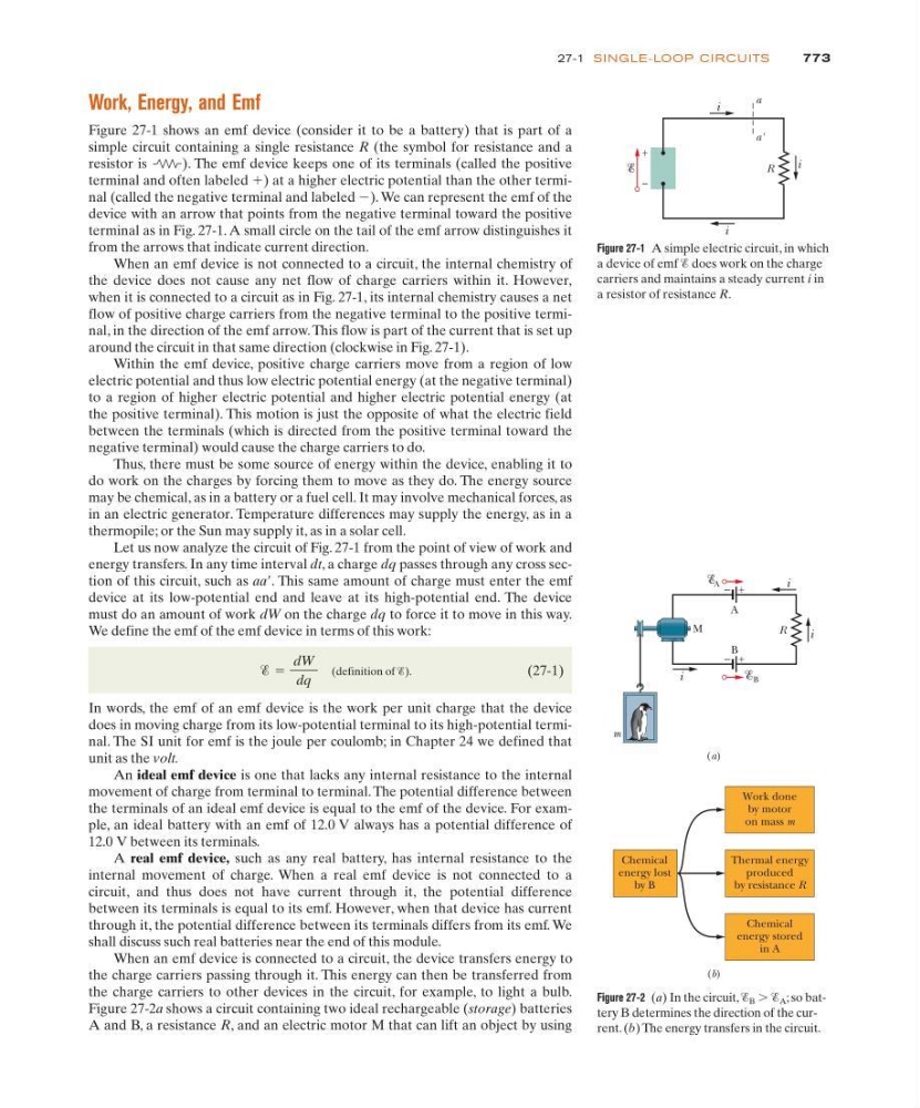
Figure 27-1 shows an emf device (consider it to be a battery) that is part of a
simple circuit containing a single resistance R (the symbol for resistance and a
resistor is
). The emf device keeps one of its terminals (called the positive
terminal and often labeled ϩ) at a higher electric potential than the other terminal (called the negative terminal and labeled Ϫ). We can represent the emf of the
device with an arrow that points from the negative terminal toward the positive
terminal as in Fig. 27-1. A small circle on the tail of the emf arrow distinguishes it
from the arrows that indicate current direction.
When an emf device is not connected to a circuit, the internal chemistry of
the device does not cause any net flow of charge carriers within it. However,
when it is connected to a circuit as in Fig. 27-1, its internal chemistry causes a net
flow of positive charge carriers from the negative terminal to the positive terminal, in the direction of the emf arrow. This flow is part of the current that is set up
around the circuit in that same direction (clockwise in Fig. 27-1).
Within the emf device, positive charge carriers move from a region of low
electric potential and thus low electric potential energy (at the negative terminal)
to a region of higher electric potential and higher electric potential energy (at
the positive terminal). This motion is just the opposite of what the electric field
between the terminals (which is directed from the positive terminal toward the
negative terminal) would cause the charge carriers to do.
Thus, there must be some source of energy within the device, enabling it to
do work on the charges by forcing them to move as they do. The energy source
may be chemical, as in a battery or a fuel cell. It may involve mechanical forces, as
in an electric generator. Temperature differences may supply the energy, as in a
thermopile; or the Sun may supply it, as in a solar cell.
Let us now analyze the circuit of Fig. 27-1 from the point of view of work and
energy transfers. In any time interval dt, a charge dq passes through any cross section of this circuit, such as aaЈ. This same amount of charge must enter the emf
device at its low-potential end and leave at its high-potential end. The device
must do an amount of work dW on the charge dq to force it to move in this way.
We define the emf of the emf device in terms of this work:
(definition of Ᏹ).
(27-1)
In words, the emf of an emf device is the work per unit charge that the device
does in moving charge from its low-potential terminal to its high-potential terminal. The SI unit for emf is the joule per coulomb; in Chapter 24 we defined that
unit as the volt.
An ideal emf device is one that lacks any internal resistance to the internal
movement of charge from terminal to terminal. The potential difference between
the terminals of an ideal emf device is equal to the emf of the device. For example, an ideal battery with an emf of 12.0 V always has a potential difference of
12.0 V between its terminals.
A real emf device, such as any real battery, has internal resistance to the
internal movement of charge. When a real emf device is not connected to a
circuit, and thus does not have current through it, the potential difference
between its terminals is equal to its emf. However, when that device has current
through it, the potential difference between its terminals differs from its emf. We
shall discuss such real batteries near the end of this module.
When an emf device is connected to a circuit, the device transfers energy to
the charge carriers passing through it. This energy can then be transferred from
the charge carriers to other devices in the circuit, for example, to light a bulb.
Figure 27-2a shows a circuit containing two ideal rechargeable (storage) batteries
A and B, a resistance R, and an electric motor M that can lift an object by using
Ᏹ ϭ
dW
dq
773
27-1 SI NG LE-LOOP CI RCU ITS
R
i
i
i
+
–
a
a'
Figure 27-1 A simple electric circuit, in which
a device of emf Ᏹ does work on the charge
carriers and maintains a steady current i in
a resistor of resistance R.
R
i
+
–
A
A
+
–
B
B
i
i
M
m
(a)
Work done
by motor
on mass m
Chemical
energy lost
by B
Thermal energy
produced
by resistance R
Chemical
energy stored
in A
(b)
Figure 27-2 (a) In the circuit, Ᏹ B Ͼ Ᏹ A ; so battery B determines the direction of the current. (b) The energy transfers in the circuit.