

energy it obtains from charge carriers in the circuit. Note that the batteries are
connected so that they tend to send charges around the circuit in opposite directions. The actual direction of the current in the circuit is determined by the
battery with the larger emf, which happens to be battery B, so the chemical
energy within battery B is decreasing as energy is transferred to the charge
carriers passing through it. However, the chemical energy within battery A is
increasing because the current in it is directed from the positive terminal to the
negative terminal. Thus, battery B is charging battery A. Battery B is also providing energy to motor M and energy that is being dissipated by resistance R.
Figure 27-2b shows all three energy transfers from battery B; each decreases that
battery’s chemical energy.
Calculating the Current in a Single-Loop Circuit
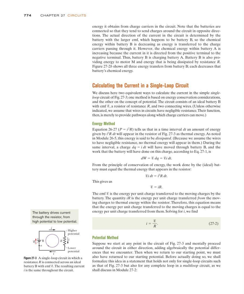
We discuss here two equivalent ways to calculate the current in the simple singleloop circuit of Fig. 27-3; one method is based on energy conservation considerations,
and the other on the concept of potential. The circuit consists of an ideal battery B
with emf Ᏹ, a resistor of resistance R, and two connecting wires. (Unless otherwise
indicated, we assume that wires in circuits have negligible resistance. Their function,
then, is merely to provide pathways along which charge carriers can move.)
Energy Method
Equation 26-27 (P ϭ i
2
R) tells us that in a time interval dt an amount of energy
given by i
2
R dt will appear in the resistor of Fig. 27-3 as thermal energy. As noted
in Module 26-5, this energy is said to be dissipated. (Because we assume the wires
to have negligible resistance, no thermal energy will appear in them.) During the
same interval, a charge dq ϭ i dt will have moved through battery B, and the
work that the battery will have done on this charge, according to Eq. 27-1, is
dW ϭ Ᏹ dq ϭ Ᏹi dt.
From the principle of conservation of energy, the work done by the (ideal) battery must equal the thermal energy that appears in the resistor:
Ᏹi dt ϭ i
2
R dt.
This gives us
Ᏹ ϭ iR.
The emf Ᏹ is the energy per unit charge transferred to the moving charges by the
battery. The quantity iR is the energy per unit charge transferred from the moving charges to thermal energy within the resistor. Therefore, this equation means
that the energy per unit charge transferred to the moving charges is equal to the
energy per unit charge transferred from them. Solving for i, we find
(27-2)
Potential Method
Suppose we start at any point in the circuit of Fig. 27-3 and mentally proceed
around the circuit in either direction, adding algebraically the potential differences that we encounter. Then when we return to our starting point, we must
also have returned to our starting potential. Before actually doing so, we shall
formalize this idea in a statement that holds not only for single-loop circuits such
as that of Fig. 27-3 but also for any complete loop in a multiloop circuit, as we
shall discuss in Module 27-2:
i ϭ
Ᏹ
R
.
774
CHAPTE R 27 CI RCU ITS
Figure 27-3 A single-loop circuit in which a
resistance R is connected across an ideal
battery B with emf Ᏹ.The resulting current
i is the same throughout the circuit.
Higher
potential
R
i
–
B
i
i
+
Lower
potential
a
The battery drives current
through the resistor, from
high potential to low potential.