

rod will be less than 0.2%. Although deformations of this size seem small, they
are important in engineering practice. (Whether a wing under load will stay on an
airplane is obviously important.)
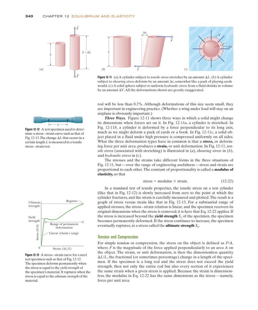
Three Ways. Figure 12-11 shows three ways in which a solid might change
its dimensions when forces act on it. In Fig. 12-11a, a cylinder is stretched. In
Fig. 12-11b, a cylinder is deformed by a force perpendicular to its long axis,
much as we might deform a pack of cards or a book. In Fig. 12-11c, a solid object placed in a fluid under high pressure is compressed uniformly on all sides.
What the three deformation types have in common is that a stress, or deforming force per unit area, produces a strain, or unit deformation. In Fig. 12-11, tensile stress (associated with stretching) is illustrated in (a), shearing stress in (b),
and hydraulic stress in (c).
The stresses and the strains take different forms in the three situations of
Fig. 12-11, but — over the range of engineering usefulness — stress and strain are
proportional to each other. The constant of proportionality is called a modulus of
elasticity, so that
stress ϭ modulus ϫ strain.
(12-22)
In a standard test of tensile properties, the tensile stress on a test cylinder
(like that in Fig. 12-12) is slowly increased from zero to the point at which the
cylinder fractures, and the strain is carefully measured and plotted. The result is a
graph of stress versus strain like that in Fig. 12-13. For a substantial range of
applied stresses, the stress – strain relation is linear, and the specimen recovers its
original dimensions when the stress is removed; it is here that Eq. 12-22 applies. If
the stress is increased beyond the yield strength S y of the specimen, the specimen
becomes permanently deformed. If the stress continues to increase, the specimen
eventually ruptures, at a stress called the ultimate strength S u .
Tension and Compression
For simple tension or compression, the stress on the object is defined as F/A,
where F is the magnitude of the force applied perpendicularly to an area A on
the object. The strain, or unit deformation, is then the dimensionless quantity
⌬L/L, the fractional (or sometimes percentage) change in a length of the specimen. If the specimen is a long rod and the stress does not exceed the yield
strength, then not only the entire rod but also every section of it experiences
the same strain when a given stress is applied. Because the strain is dimensionless, the modulus in Eq. 12-22 has the same dimensions as the stress — namely,
force per unit area.
340
CHAPTE R 12 EQU I LI B R I U M AN D E L ASTICITY
Figure 12-11 (a) A cylinder subject to tensile stress stretches by an amount ⌬L. (b) A cylinder
subject to shearing stress deforms by an amount ⌬x, somewhat like a pack of playing cards
would. (c) A solid sphere subject to uniform hydraulic stress from a fluid shrinks in volume
by an amount ⌬V.All the deformations shown are greatly exaggerated.
L
Figure 12-12 A test specimen used to determine a stress – strain curve such as that of
Fig. 12-13.The change ⌬L that occurs in a
certain length L is measured in a tensile
stress – strain test.
Figure 12-13 A stress – strain curve for a steel
test specimen such as that of Fig. 12-12.
The specimen deforms permanently when
the stress is equal to the yield strength of
the specimen’s material. It ruptures when the
stress is equal to the ultimate strength of the
material.
Ultimate
strength
Yield
strength
Range of permanent
deformation
Rupture
Linear (elastic) range
Strain (∆L/L)
0
Stress (F/A)
∆V
V
(c)
(a)
L + ∆L
L
F
F
(b)
L
∆x
F
F
are important in engineering practice. (Whether a wing under load will stay on an
airplane is obviously important.)
Three Ways. Figure 12-11 shows three ways in which a solid might change
its dimensions when forces act on it. In Fig. 12-11a, a cylinder is stretched. In
Fig. 12-11b, a cylinder is deformed by a force perpendicular to its long axis,
much as we might deform a pack of cards or a book. In Fig. 12-11c, a solid object placed in a fluid under high pressure is compressed uniformly on all sides.
What the three deformation types have in common is that a stress, or deforming force per unit area, produces a strain, or unit deformation. In Fig. 12-11, tensile stress (associated with stretching) is illustrated in (a), shearing stress in (b),
and hydraulic stress in (c).
The stresses and the strains take different forms in the three situations of
Fig. 12-11, but — over the range of engineering usefulness — stress and strain are
proportional to each other. The constant of proportionality is called a modulus of
elasticity, so that
stress ϭ modulus ϫ strain.
(12-22)
In a standard test of tensile properties, the tensile stress on a test cylinder
(like that in Fig. 12-12) is slowly increased from zero to the point at which the
cylinder fractures, and the strain is carefully measured and plotted. The result is a
graph of stress versus strain like that in Fig. 12-13. For a substantial range of
applied stresses, the stress – strain relation is linear, and the specimen recovers its
original dimensions when the stress is removed; it is here that Eq. 12-22 applies. If
the stress is increased beyond the yield strength S y of the specimen, the specimen
becomes permanently deformed. If the stress continues to increase, the specimen
eventually ruptures, at a stress called the ultimate strength S u .
Tension and Compression
For simple tension or compression, the stress on the object is defined as F/A,
where F is the magnitude of the force applied perpendicularly to an area A on
the object. The strain, or unit deformation, is then the dimensionless quantity
⌬L/L, the fractional (or sometimes percentage) change in a length of the specimen. If the specimen is a long rod and the stress does not exceed the yield
strength, then not only the entire rod but also every section of it experiences
the same strain when a given stress is applied. Because the strain is dimensionless, the modulus in Eq. 12-22 has the same dimensions as the stress — namely,
force per unit area.
340
CHAPTE R 12 EQU I LI B R I U M AN D E L ASTICITY
Figure 12-11 (a) A cylinder subject to tensile stress stretches by an amount ⌬L. (b) A cylinder
subject to shearing stress deforms by an amount ⌬x, somewhat like a pack of playing cards
would. (c) A solid sphere subject to uniform hydraulic stress from a fluid shrinks in volume
by an amount ⌬V.All the deformations shown are greatly exaggerated.
L
Figure 12-12 A test specimen used to determine a stress – strain curve such as that of
Fig. 12-13.The change ⌬L that occurs in a
certain length L is measured in a tensile
stress – strain test.
Figure 12-13 A stress – strain curve for a steel
test specimen such as that of Fig. 12-12.
The specimen deforms permanently when
the stress is equal to the yield strength of
the specimen’s material. It ruptures when the
stress is equal to the ultimate strength of the
material.
Ultimate
strength
Yield
strength
Range of permanent
deformation
Rupture
Linear (elastic) range
Strain (∆L/L)
0
Stress (F/A)
∆V
V
(c)
(a)
L + ∆L
L
F
F
(b)
L
∆x
F
F