

228 Th to
253 Es and 84 fission products (83 nuclides treated explicitly and 1 lumped
fission product) were treated. In the core neutronic calculation, the 12-energy
group, three-dimensional neutron flux was obtained by solving the diffusion equation with 1 mesh for each fuel bundle in the horizontal direction and 34 meshes in
the vertical direction.
In the thermal hydraulic calculation, the in-channel coolant flow rate, the
two-phase flow pressure drop, and the axial void fraction distribution were calculated based on the power distribution obtained by the core neutronic calculation, so
that the pressure drops between fuel bundles were balanced. The core neutronic
calculation and the thermal hydraulic calculation were iterated until the power
distribution and in-channel coolant flow distribution converged.
The void reactivity coefficient was evaluated by decreasing the core coolant flow
rate to 95 % of the rated flow and dividing the change of the neutron multiplication
factor by the change of core averaged void fraction, from the respective values at
the rated flow.
14.2.3 RBWR-AC
The axial fuel bundle configuration of the RBWR-AC is shown in Fig. 14.5. The
axial configuration is the parfait core, where an internal blanket (520 mm) of
depleted uranium oxide is placed between two fissile zones (upper, 280 mm;
lower, 193 mm). The upper and lower blankets (70 and 280 mm) are attached
above and below the upper and lower fissile zones, respectively.
The neutron absorber zones are placed above and below the fuel zone (fissile and
blanket) to increase the margin to maintain the negative void reactivity coefficient.
The upper neutron absorber zone is composed of the neutron absorber rods placed
between the plenums, which are connected to the fuel rods. The neutron absorber
rods are filled with B 4 C pellets in a sealed tube with an outside diameter of 7.7 mm.
0
0.5
1
0
1
2
3
Volume ratio (H 2 O/fuel)
Breeding ratio*
Conventional
BWR
Once-through
RBWR-TB2
Multi-recycling
by adding fissile
TRUs from LWR
Multi-recycling with fissile
TRUs produced by itself
RBWR-TB
RBWR-AC
* Ratio of discharged amount of fissile materials to charged amount of fissile materials
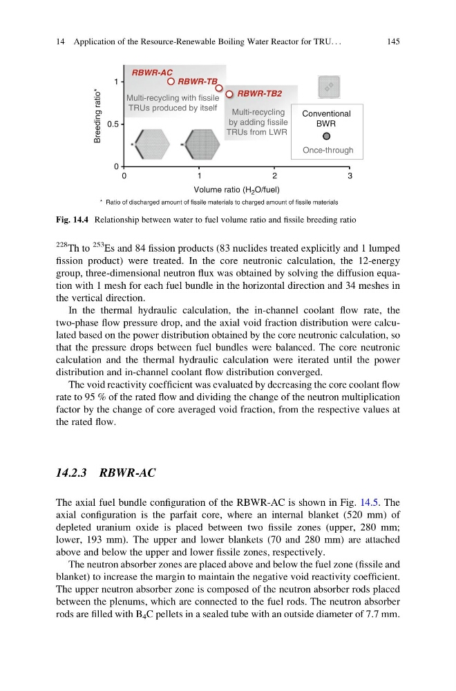
Fig. 14.4 Relationship between water to fuel volume ratio and fissile breeding ratio
14 Application of the Resource-Renewable Boiling Water Reactor for TRU. . .
145
253 Es and 84 fission products (83 nuclides treated explicitly and 1 lumped
fission product) were treated. In the core neutronic calculation, the 12-energy
group, three-dimensional neutron flux was obtained by solving the diffusion equation with 1 mesh for each fuel bundle in the horizontal direction and 34 meshes in
the vertical direction.
In the thermal hydraulic calculation, the in-channel coolant flow rate, the
two-phase flow pressure drop, and the axial void fraction distribution were calculated based on the power distribution obtained by the core neutronic calculation, so
that the pressure drops between fuel bundles were balanced. The core neutronic
calculation and the thermal hydraulic calculation were iterated until the power
distribution and in-channel coolant flow distribution converged.
The void reactivity coefficient was evaluated by decreasing the core coolant flow
rate to 95 % of the rated flow and dividing the change of the neutron multiplication
factor by the change of core averaged void fraction, from the respective values at
the rated flow.
14.2.3 RBWR-AC
The axial fuel bundle configuration of the RBWR-AC is shown in Fig. 14.5. The
axial configuration is the parfait core, where an internal blanket (520 mm) of
depleted uranium oxide is placed between two fissile zones (upper, 280 mm;
lower, 193 mm). The upper and lower blankets (70 and 280 mm) are attached
above and below the upper and lower fissile zones, respectively.
The neutron absorber zones are placed above and below the fuel zone (fissile and
blanket) to increase the margin to maintain the negative void reactivity coefficient.
The upper neutron absorber zone is composed of the neutron absorber rods placed
between the plenums, which are connected to the fuel rods. The neutron absorber
rods are filled with B 4 C pellets in a sealed tube with an outside diameter of 7.7 mm.
0
0.5
1
0
1
2
3
Volume ratio (H 2 O/fuel)
Breeding ratio*
Conventional
BWR
Once-through
RBWR-TB2
Multi-recycling
by adding fissile
TRUs from LWR
Multi-recycling with fissile
TRUs produced by itself
RBWR-TB
RBWR-AC
* Ratio of discharged amount of fissile materials to charged amount of fissile materials
Fig. 14.4 Relationship between water to fuel volume ratio and fissile breeding ratio
14 Application of the Resource-Renewable Boiling Water Reactor for TRU. . .
145