

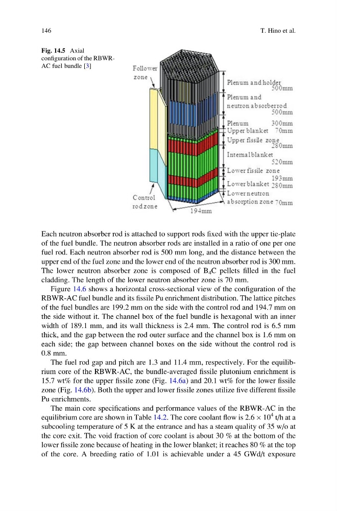
Each neutron absorber rod is attached to support rods fixed with the upper tie-plate
of the fuel bundle. The neutron absorber rods are installed in a ratio of one per one
fuel rod. Each neutron absorber rod is 500 mm long, and the distance between the
upper end of the fuel zone and the lower end of the neutron absorber rod is 300 mm.
The lower neutron absorber zone is composed of B 4 C pellets filled in the fuel
cladding. The length of the lower neutron absorber zone is 70 mm.
Figure 14.6 shows a horizontal cross-sectional view of the configuration of the
RBWR-AC fuel bundle and its fissile Pu enrichment distribution. The lattice pitches
of the fuel bundles are 199.2 mm on the side with the control rod and 194.7 mm on
the side without it. The channel box of the fuel bundle is hexagonal with an inner
width of 189.1 mm, and its wall thickness is 2.4 mm. The control rod is 6.5 mm
thick, and the gap between the rod outer surface and the channel box is 1.6 mm on
each side; the gap between channel boxes on the side without the control rod is
0.8 mm.
The fuel rod gap and pitch are 1.3 and 11.4 mm, respectively. For the equilibrium core of the RBWR-AC, the bundle-averaged fissile plutonium enrichment is
15.7 wt% for the upper fissile zone (Fig. 14.6a) and 20.1 wt% for the lower fissile
zone (Fig. 14.6b). Both the upper and lower fissile zones utilize five different fissile
Pu enrichments.
The main core specifications and performance values of the RBWR-AC in the
equilibrium core are shown in Table 14.2. The core coolant flow is 2.6 Â 10
4 t/h at a
subcooling temperature of 5 K at the entrance and has a steam quality of 35 w/o at
the core exit. The void fraction of core coolant is about 30 % at the bottom of the
lower fissile zone because of heating in the lower blanket; it reaches 80 % at the top
of the core. A breeding ratio of 1.01 is achievable under a 45 GWd/t exposure
Fig. 14.5 Axial
configuration of the RBWRAC fuel bundle [3]
146
T. Hino et al.
of the fuel bundle. The neutron absorber rods are installed in a ratio of one per one
fuel rod. Each neutron absorber rod is 500 mm long, and the distance between the
upper end of the fuel zone and the lower end of the neutron absorber rod is 300 mm.
The lower neutron absorber zone is composed of B 4 C pellets filled in the fuel
cladding. The length of the lower neutron absorber zone is 70 mm.
Figure 14.6 shows a horizontal cross-sectional view of the configuration of the
RBWR-AC fuel bundle and its fissile Pu enrichment distribution. The lattice pitches
of the fuel bundles are 199.2 mm on the side with the control rod and 194.7 mm on
the side without it. The channel box of the fuel bundle is hexagonal with an inner
width of 189.1 mm, and its wall thickness is 2.4 mm. The control rod is 6.5 mm
thick, and the gap between the rod outer surface and the channel box is 1.6 mm on
each side; the gap between channel boxes on the side without the control rod is
0.8 mm.
The fuel rod gap and pitch are 1.3 and 11.4 mm, respectively. For the equilibrium core of the RBWR-AC, the bundle-averaged fissile plutonium enrichment is
15.7 wt% for the upper fissile zone (Fig. 14.6a) and 20.1 wt% for the lower fissile
zone (Fig. 14.6b). Both the upper and lower fissile zones utilize five different fissile
Pu enrichments.
The main core specifications and performance values of the RBWR-AC in the
equilibrium core are shown in Table 14.2. The core coolant flow is 2.6 Â 10
4 t/h at a
subcooling temperature of 5 K at the entrance and has a steam quality of 35 w/o at
the core exit. The void fraction of core coolant is about 30 % at the bottom of the
lower fissile zone because of heating in the lower blanket; it reaches 80 % at the top
of the core. A breeding ratio of 1.01 is achievable under a 45 GWd/t exposure
Fig. 14.5 Axial
configuration of the RBWRAC fuel bundle [3]
146
T. Hino et al.