

494
7 Applications: Pebble Flow Optimizations
is also helpful, but the effect is relatively limited based on the difference between
“μ p−w = 0.3, μ p− p = 0.5” and “μ p−w = 0.3, μ p− p = 0.05”.
7.5.5 Friction Control in Practical Pebble Bed
Reducing friction in a pebble flow has been proven to be very helpful in improving
the flow performance in pebble beds. Primarily, confining the particle–wall friction
under a certain level can ensure the preferred flow pattern required by the nuclear
application. The following discussions focus on the strategy of the particle–wall
friction control for different parts of the pebble bed. The particle–particle friction
coefficient is set to a fixed value 0.5 in the following simulated cases .
In HTGR engineering, the geometrical design of the pebble bed is determined. The
bed configuration is like a combination of a cylinder body and a hopper bottom (refer
to Fig. 7.32). There is always a balance between the return and the cost to achieve in
engineering. Thus, the friction impact of the cylinder and the hopper on the flow field
is compared, and the more critical part of the process is found. Simulation results
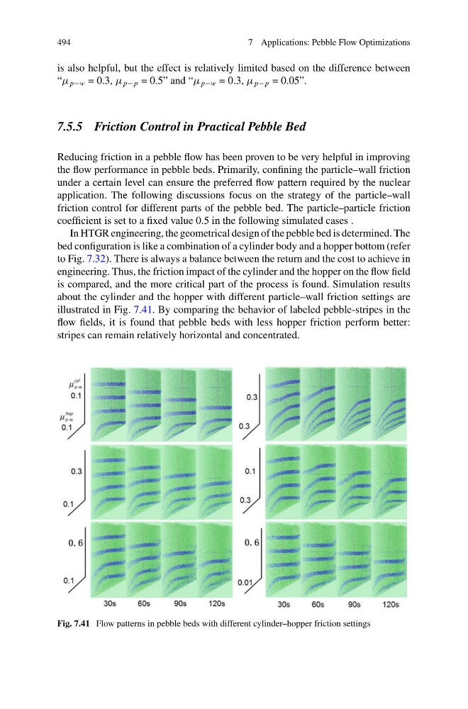
about the cylinder and the hopper with different particle–wall friction settings are
illustrated in Fig. 7.41. By comparing the behavior of labeled pebble-stripes in the
flow fields, it is found that pebble beds with less hopper friction perform better:
stripes can remain relatively horizontal and concentrated.
Fig. 7.41 Flow patterns in pebble beds with different cylinder–hopper friction settings
7 Applications: Pebble Flow Optimizations
is also helpful, but the effect is relatively limited based on the difference between
“μ p−w = 0.3, μ p− p = 0.5” and “μ p−w = 0.3, μ p− p = 0.05”.
7.5.5 Friction Control in Practical Pebble Bed
Reducing friction in a pebble flow has been proven to be very helpful in improving
the flow performance in pebble beds. Primarily, confining the particle–wall friction
under a certain level can ensure the preferred flow pattern required by the nuclear
application. The following discussions focus on the strategy of the particle–wall
friction control for different parts of the pebble bed. The particle–particle friction
coefficient is set to a fixed value 0.5 in the following simulated cases .
In HTGR engineering, the geometrical design of the pebble bed is determined. The
bed configuration is like a combination of a cylinder body and a hopper bottom (refer
to Fig. 7.32). There is always a balance between the return and the cost to achieve in
engineering. Thus, the friction impact of the cylinder and the hopper on the flow field
is compared, and the more critical part of the process is found. Simulation results
about the cylinder and the hopper with different particle–wall friction settings are
illustrated in Fig. 7.41. By comparing the behavior of labeled pebble-stripes in the
flow fields, it is found that pebble beds with less hopper friction perform better:
stripes can remain relatively horizontal and concentrated.
Fig. 7.41 Flow patterns in pebble beds with different cylinder–hopper friction settings