

7.3 Flow-Corrective Insert Optimization
461
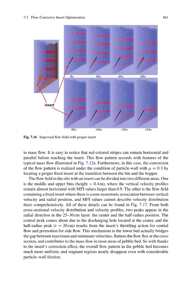
Fig. 7.16 Improved flow field with proper insert
to mass flow. It is easy to notice that red-colored stripes can remain horizontal and
parallel before reaching the insert. This flow pattern accords with features of the
typical mass flow illustrated in Fig. 7.12a. Furthermore, in this case, the conversion
of the flow pattern is realized under the condition of particle-wall with μ = 0.3 by
locating a proper fixed insert at the transition between the bin and the hopper.
The flow field in the silo with an insert can be divided into two different areas. One
is the middle and upper bins (height > 0.4 m), where the vertical velocity profiles
remain almost horizontal with MFI values larger than 0.9. The other is the flow field
containing a fixed insert where there is a non-monotonic association between vertical
velocity and radial position, and MFI values cannot describe velocity distribution
there comprehensively. All of these details can be found in Fig. 7.17. From both
cross-sectional velocity distribution and velocity profiles, two peaks appear in the
radial direction in the 25–30 cm layer: the center and the half-radius position. The
central peak comes about due to the discharging hole located at the center, and the
half-radius peak (r = 20 cm) results from the insert’s throttling action for central
flow and promotion for side flow. This mechanism in the lower bed actually bridges
the gap between maximum and minimum velocities, flattens the flow flux at the cross
section, and contributes to the mass flow in most areas of pebble bed. So with thanks
to the insert’s correction effect, the overall flow pattern in the pebble bed becomes
much more uniform, and stagnant regions nearly disappear even with considerable
particle–wall friction.
461
Fig. 7.16 Improved flow field with proper insert
to mass flow. It is easy to notice that red-colored stripes can remain horizontal and
parallel before reaching the insert. This flow pattern accords with features of the
typical mass flow illustrated in Fig. 7.12a. Furthermore, in this case, the conversion
of the flow pattern is realized under the condition of particle-wall with μ = 0.3 by
locating a proper fixed insert at the transition between the bin and the hopper.
The flow field in the silo with an insert can be divided into two different areas. One
is the middle and upper bins (height > 0.4 m), where the vertical velocity profiles
remain almost horizontal with MFI values larger than 0.9. The other is the flow field
containing a fixed insert where there is a non-monotonic association between vertical
velocity and radial position, and MFI values cannot describe velocity distribution
there comprehensively. All of these details can be found in Fig. 7.17. From both
cross-sectional velocity distribution and velocity profiles, two peaks appear in the
radial direction in the 25–30 cm layer: the center and the half-radius position. The
central peak comes about due to the discharging hole located at the center, and the
half-radius peak (r = 20 cm) results from the insert’s throttling action for central
flow and promotion for side flow. This mechanism in the lower bed actually bridges
the gap between maximum and minimum velocities, flattens the flow flux at the cross
section, and contributes to the mass flow in most areas of pebble bed. So with thanks
to the insert’s correction effect, the overall flow pattern in the pebble bed becomes
much more uniform, and stagnant regions nearly disappear even with considerable
particle–wall friction.