

460
7 Applications: Pebble Flow Optimizations
without reducing particle–wall friction, perhaps the effort should not be dedicated to
processing contact surfaces. Utilizing a flow-corrective insert may be a better option
for creating a uniform flow field. The type of insert adopted here belongs to the conein-cone type, which is presented in the right side of Fig. ( 7.10). Although some crucial
suggestions about the cone-in-cone insert design have been obtained [5], it is still
difficult to directly apply them to specific cases because of diverse configurations
of silos and physical properties of particles. Moreover, the flow-corrective insert has
not been utilized for the controlled-discharge process in nuclear engineering ever
before.
There are some tips concluded from experiments for the cone-in-cone insert design
[13–15]. The inclination of the internal cone to the vertical (α in ) had to be smaller
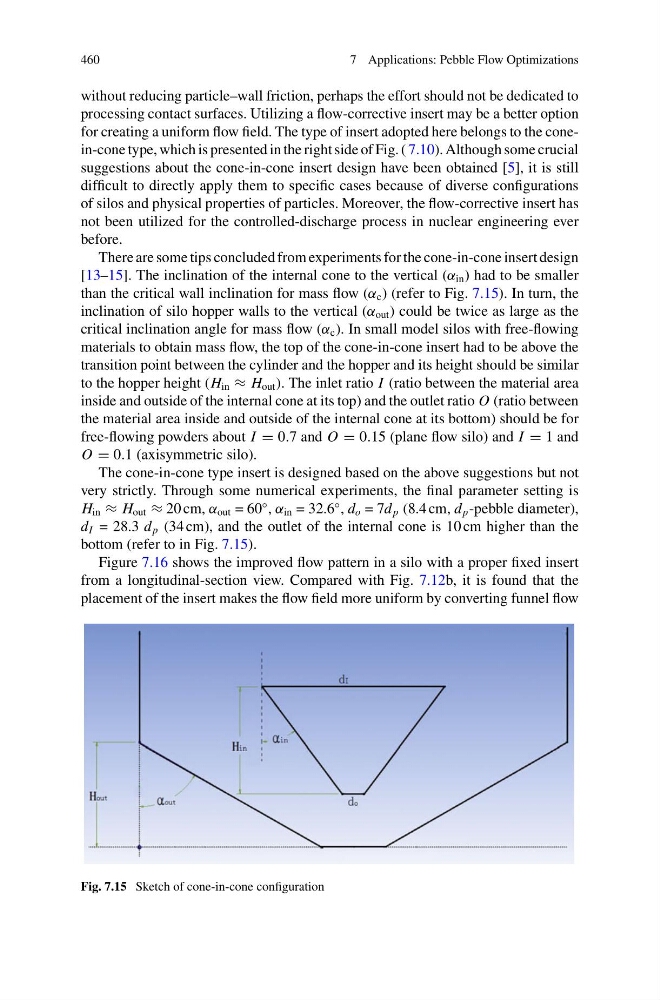
than the critical wall inclination for mass flow (α c ) (refer to Fig. 7.15). In turn, the
inclination of silo hopper walls to the vertical (α out ) could be twice as large as the
critical inclination angle for mass flow (α c ). In small model silos with free-flowing
materials to obtain mass flow, the top of the cone-in-cone insert had to be above the
transition point between the cylinder and the hopper and its height should be similar
to the hopper height (H in ≈ H out ). The inlet ratio I (ratio between the material area
inside and outside of the internal cone at its top) and the outlet ratio O (ratio between
the material area inside and outside of the internal cone at its bottom) should be for
free-flowing powders about I = 0.7 and O = 0.15 (plane flow silo) and I = 1 and
O = 0.1 (axisymmetric silo).
The cone-in-cone type insert is designed based on the above suggestions but not
very strictly. Through some numerical experiments, the final parameter setting is
H in ≈ H out ≈ 20 cm, α out = 60
◦ , α in = 32.6
◦ , d o = 7d p (8.4 cm, d p -pebble diameter),
d I = 28.3 d p (34 cm), and the outlet of the internal cone is 10 cm higher than the
bottom (refer to in Fig. 7.15).
Figure 7.16 shows the improved flow pattern in a silo with a proper fixed insert
from a longitudinal-section view. Compared with Fig. 7.12b, it is found that the
placement of the insert makes the flow field more uniform by converting funnel flow
Fig. 7.15 Sketch of cone-in-cone configuration
7 Applications: Pebble Flow Optimizations
without reducing particle–wall friction, perhaps the effort should not be dedicated to
processing contact surfaces. Utilizing a flow-corrective insert may be a better option
for creating a uniform flow field. The type of insert adopted here belongs to the conein-cone type, which is presented in the right side of Fig. ( 7.10). Although some crucial
suggestions about the cone-in-cone insert design have been obtained [5], it is still
difficult to directly apply them to specific cases because of diverse configurations
of silos and physical properties of particles. Moreover, the flow-corrective insert has
not been utilized for the controlled-discharge process in nuclear engineering ever
before.
There are some tips concluded from experiments for the cone-in-cone insert design
[13–15]. The inclination of the internal cone to the vertical (α in ) had to be smaller
than the critical wall inclination for mass flow (α c ) (refer to Fig. 7.15). In turn, the
inclination of silo hopper walls to the vertical (α out ) could be twice as large as the
critical inclination angle for mass flow (α c ). In small model silos with free-flowing
materials to obtain mass flow, the top of the cone-in-cone insert had to be above the
transition point between the cylinder and the hopper and its height should be similar
to the hopper height (H in ≈ H out ). The inlet ratio I (ratio between the material area
inside and outside of the internal cone at its top) and the outlet ratio O (ratio between
the material area inside and outside of the internal cone at its bottom) should be for
free-flowing powders about I = 0.7 and O = 0.15 (plane flow silo) and I = 1 and
O = 0.1 (axisymmetric silo).
The cone-in-cone type insert is designed based on the above suggestions but not
very strictly. Through some numerical experiments, the final parameter setting is
H in ≈ H out ≈ 20 cm, α out = 60
◦ , α in = 32.6
◦ , d o = 7d p (8.4 cm, d p -pebble diameter),
d I = 28.3 d p (34 cm), and the outlet of the internal cone is 10 cm higher than the
bottom (refer to in Fig. 7.15).
Figure 7.16 shows the improved flow pattern in a silo with a proper fixed insert
from a longitudinal-section view. Compared with Fig. 7.12b, it is found that the
placement of the insert makes the flow field more uniform by converting funnel flow
Fig. 7.15 Sketch of cone-in-cone configuration