

3.1.5 The Zajfman Trap
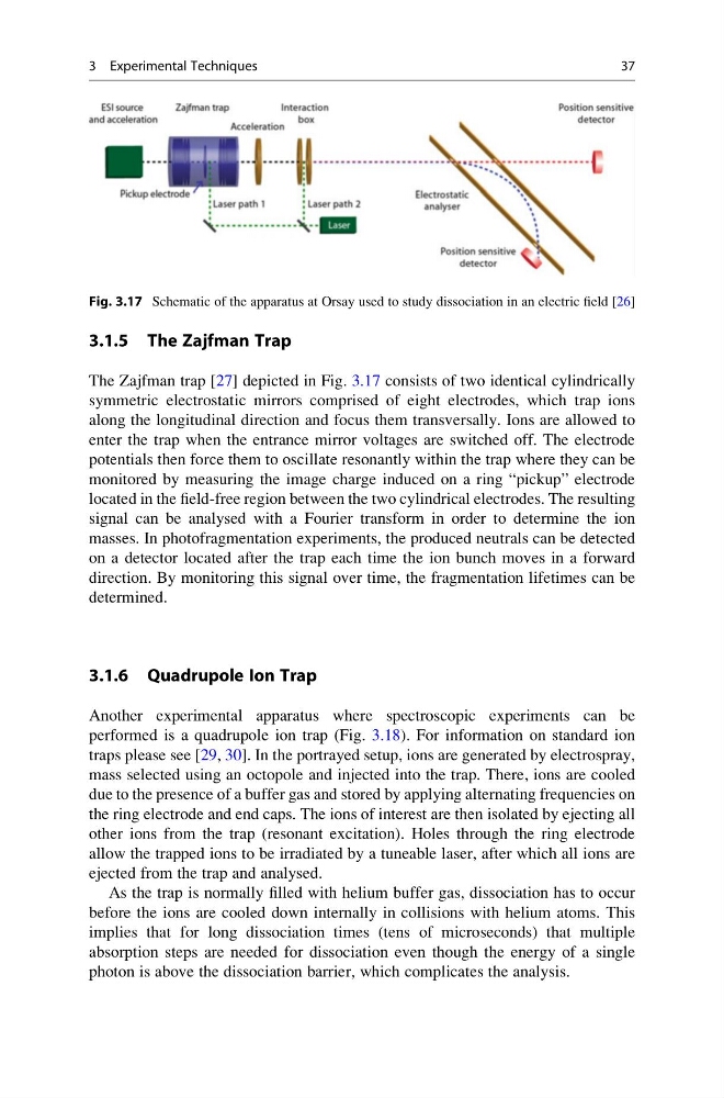
The Zajfman trap [27] depicted in Fig. 3.17 consists of two identical cylindrically
symmetric electrostatic mirrors comprised of eight electrodes, which trap ions
along the longitudinal direction and focus them transversally. Ions are allowed to
enter the trap when the entrance mirror voltages are switched off. The electrode
potentials then force them to oscillate resonantly within the trap where they can be
monitored by measuring the image charge induced on a ring “pickup” electrode
located in the field-free region between the two cylindrical electrodes. The resulting
signal can be analysed with a Fourier transform in order to determine the ion
masses. In photofragmentation experiments, the produced neutrals can be detected
on a detector located after the trap each time the ion bunch moves in a forward
direction. By monitoring this signal over time, the fragmentation lifetimes can be
determined.
3.1.6 Quadrupole Ion Trap
Another experimental apparatus where spectroscopic experiments can be
performed is a quadrupole ion trap (Fig. 3.18). For information on standard ion
traps please see [29, 30]. In the portrayed setup, ions are generated by electrospray,
mass selected using an octopole and injected into the trap. There, ions are cooled
due to the presence of a buffer gas and stored by applying alternating frequencies on
the ring electrode and end caps. The ions of interest are then isolated by ejecting all
other ions from the trap (resonant excitation). Holes through the ring electrode
allow the trapped ions to be irradiated by a tuneable laser, after which all ions are
ejected from the trap and analysed.
As the trap is normally filled with helium buffer gas, dissociation has to occur
before the ions are cooled down internally in collisions with helium atoms. This
implies that for long dissociation times (tens of microseconds) that multiple
absorption steps are needed for dissociation even though the energy of a single
photon is above the dissociation barrier, which complicates the analysis.
Fig. 3.17 Schematic of the apparatus at Orsay used to study dissociation in an electric field [26]
3 Experimental Techniques
37
The Zajfman trap [27] depicted in Fig. 3.17 consists of two identical cylindrically
symmetric electrostatic mirrors comprised of eight electrodes, which trap ions
along the longitudinal direction and focus them transversally. Ions are allowed to
enter the trap when the entrance mirror voltages are switched off. The electrode
potentials then force them to oscillate resonantly within the trap where they can be
monitored by measuring the image charge induced on a ring “pickup” electrode
located in the field-free region between the two cylindrical electrodes. The resulting
signal can be analysed with a Fourier transform in order to determine the ion
masses. In photofragmentation experiments, the produced neutrals can be detected
on a detector located after the trap each time the ion bunch moves in a forward
direction. By monitoring this signal over time, the fragmentation lifetimes can be
determined.
3.1.6 Quadrupole Ion Trap
Another experimental apparatus where spectroscopic experiments can be
performed is a quadrupole ion trap (Fig. 3.18). For information on standard ion
traps please see [29, 30]. In the portrayed setup, ions are generated by electrospray,
mass selected using an octopole and injected into the trap. There, ions are cooled
due to the presence of a buffer gas and stored by applying alternating frequencies on
the ring electrode and end caps. The ions of interest are then isolated by ejecting all
other ions from the trap (resonant excitation). Holes through the ring electrode
allow the trapped ions to be irradiated by a tuneable laser, after which all ions are
ejected from the trap and analysed.
As the trap is normally filled with helium buffer gas, dissociation has to occur
before the ions are cooled down internally in collisions with helium atoms. This
implies that for long dissociation times (tens of microseconds) that multiple
absorption steps are needed for dissociation even though the energy of a single
photon is above the dissociation barrier, which complicates the analysis.
Fig. 3.17 Schematic of the apparatus at Orsay used to study dissociation in an electric field [26]
3 Experimental Techniques
37