

534
V. N. Pustovit and T. V. Shahbazyan
yielding
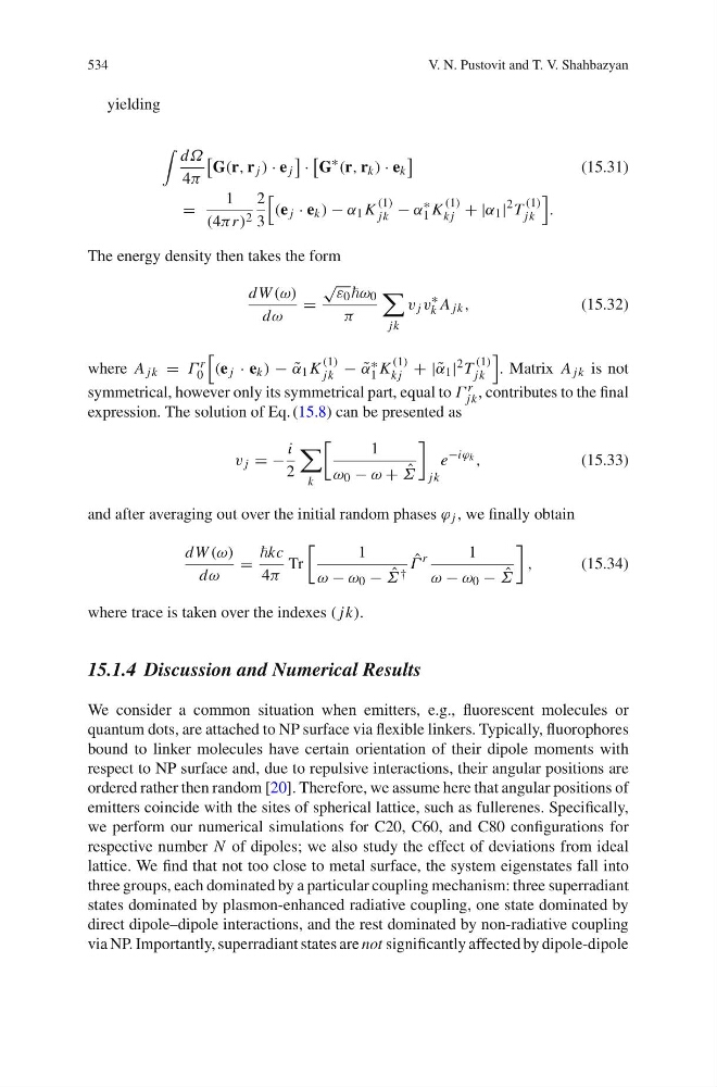
dΩ
4π
G(r, r j ) · e j
·
G
∗
(r, r k ) · e k
(15.31)
=
1
(4πr ) 2
2
3
(e j · e k ) − α 1 K
(1)
jk − α
∗
1 K
(1)
k j + |α 1 |
2 T
(1)
jk
.
The energy density then takes the form
dW (ω)
dω
=
≥
ε 0 ω 0
π
jk
v j v
∗
k A jk ,
(15.32)
where A jk = Γ r
0
(e j · e k ) − ˜
α 1 K
(1)
jk − ˜
α ∗
1 K
(1)
k j + | ˜
α 1 | 2 T
(1)
jk
. Matrix A jk is not
symmetrical, however only its symmetrical part, equal to Γ r
jk , contributes to the final
expression. The solution of Eq. (15.8) can be presented as
v j = −
i
2
k
1
ω 0 − ω + ˆ
Σ
jk
e
−iϕ k ,
(15.33)
and after averaging out over the initial random phases ϕ j , we finally obtain
dW (ω)
dω
=
kc
4π
Tr
1
ω − ω 0 − ˆ
Σ †
ˆ
Γ
r
1
ω − ω 0 − ˆ
Σ
,
(15.34)
where trace is taken over the indexes ( jk).
15.1.4 Discussion and Numerical Results
We consider a common situation when emitters, e.g., fluorescent molecules or
quantum dots, are attached to NP surface via flexible linkers. Typically, fluorophores
bound to linker molecules have certain orientation of their dipole moments with
respect to NP surface and, due to repulsive interactions, their angular positions are
ordered rather then random [20]. Therefore, we assume here that angular positions of
emitters coincide with the sites of spherical lattice, such as fullerenes. Specifically,
we perform our numerical simulations for C20, C60, and C80 configurations for
respective number N of dipoles; we also study the effect of deviations from ideal
lattice. We find that not too close to metal surface, the system eigenstates fall into
three groups, each dominated by a particular coupling mechanism: three superradiant
states dominated by plasmon-enhanced radiative coupling, one state dominated by
direct dipole–dipole interactions, and the rest dominated by non-radiative coupling
via NP. Importantly, superradiant states are not significantly affected by dipole-dipole
V. N. Pustovit and T. V. Shahbazyan
yielding
dΩ
4π
G(r, r j ) · e j
·
G
∗
(r, r k ) · e k
(15.31)
=
1
(4πr ) 2
2
3
(e j · e k ) − α 1 K
(1)
jk − α
∗
1 K
(1)
k j + |α 1 |
2 T
(1)
jk
.
The energy density then takes the form
dW (ω)
dω
=
≥
ε 0 ω 0
π
jk
v j v
∗
k A jk ,
(15.32)
where A jk = Γ r
0
(e j · e k ) − ˜
α 1 K
(1)
jk − ˜
α ∗
1 K
(1)
k j + | ˜
α 1 | 2 T
(1)
jk
. Matrix A jk is not
symmetrical, however only its symmetrical part, equal to Γ r
jk , contributes to the final
expression. The solution of Eq. (15.8) can be presented as
v j = −
i
2
k
1
ω 0 − ω + ˆ
Σ
jk
e
−iϕ k ,
(15.33)
and after averaging out over the initial random phases ϕ j , we finally obtain
dW (ω)
dω
=
kc
4π
Tr
1
ω − ω 0 − ˆ
Σ †
ˆ
Γ
r
1
ω − ω 0 − ˆ
Σ
,
(15.34)
where trace is taken over the indexes ( jk).
15.1.4 Discussion and Numerical Results
We consider a common situation when emitters, e.g., fluorescent molecules or
quantum dots, are attached to NP surface via flexible linkers. Typically, fluorophores
bound to linker molecules have certain orientation of their dipole moments with
respect to NP surface and, due to repulsive interactions, their angular positions are
ordered rather then random [20]. Therefore, we assume here that angular positions of
emitters coincide with the sites of spherical lattice, such as fullerenes. Specifically,
we perform our numerical simulations for C20, C60, and C80 configurations for
respective number N of dipoles; we also study the effect of deviations from ideal
lattice. We find that not too close to metal surface, the system eigenstates fall into
three groups, each dominated by a particular coupling mechanism: three superradiant
states dominated by plasmon-enhanced radiative coupling, one state dominated by
direct dipole–dipole interactions, and the rest dominated by non-radiative coupling
via NP. Importantly, superradiant states are not significantly affected by dipole-dipole