

13 Spinoptics in Plasmonics
491
Fig. 13.19f, g. In the observed interference patterns of the spin-flip components, two
additional fringes emerge, indicating two phase dislocations (see the guiding lines
in Fig. 13.19f, g). When the incident spin state alters , the antisymmetric fork-like
picture is reversed. The experimental patterns with an incident spin of λ = ±1 are
similar to the calculated patterns resulting from the scalar interference of two identical
optical vortices with topological charges of l = ±2, respectively (Figs. 13.19d, e).
The spin-dependent fringe patterns of a similar element with m = −1 (Fig. 13.19c)
were also observed (not shown) to verify that the helicity of the phase dislocation
corresponds to the rotation handedness of the nanorods. Moreover, the interference
pattern of the ballistic component did not comprise a phase dislocation, indicating
zero orbital AM. Each of the phase dislocations of the spin-flip components predicted
by the calculated patterns (triple fork, see Figs. 13.19d, e), breaks in the experiment
into a pair of fundamental phase dislocations (double fork, see Figs. 13.19f, g). The
non-generic vortex collapse to generic vortices is in accordance with the prediction
in Ref. [76]; therefore, the topological charge of the beam in this experiment is
given by the number of the fundamental phase dislocations, resulting in l = ±2.
As the orbital AM is directly linked to the azimuthal momentum correction Δk π
via l = − (1/2α )
Δk π dϕ , the observed optical field with l = 2mλ provides the
evidence for a spin-Hall momentum deviation of Δk π = −2mλ /r o . Since the unit
cell anisotropy of the chain for m = 1 follows its curvature (τ = π), the OSHE-LA
in this case is equivalent to the OSHE-LI one. However, by m-fold rotation of the
nanorods’ orientation one can obtain m-fold magnification of the OSHE. Circular
chains of annular apertures and rotating nanorods with m = ±2 were analyzed using
the same interference method to experimentally demonstrate that the topological
charge of the spin-flip component equals l = 2λ and 2mλ for the OSHE-LI and
OSHE-LA, respectively.
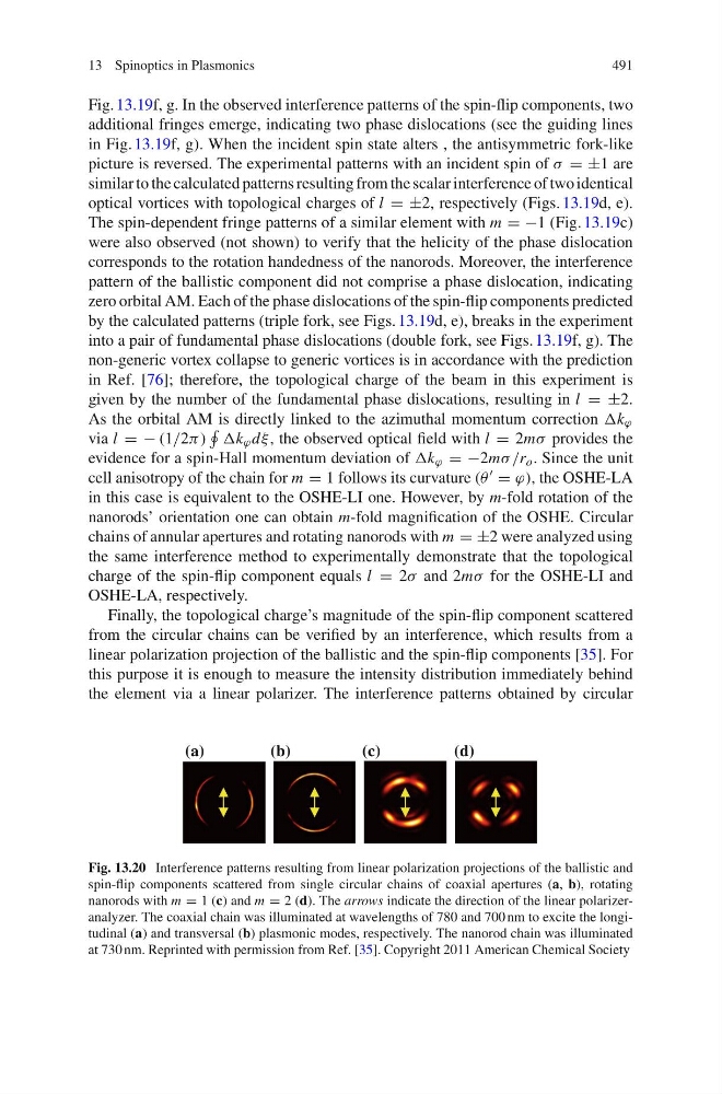
Finally, the topological charge’s magnitude of the spin-flip component scattered
from the circular chains can be verified by an interference, which results from a
linear polarization projection of the ballistic and the spin-flip components [35]. For
this purpose it is enough to measure the intensity distribution immediately behind
the element via a linear polarizer. The interference patterns obtained by circular
(a)
(b)
(c)
(d)
Fig. 13.20 Interference patterns resulting from linear polarization projections of the ballistic and
spin-flip components scattered from single circular chains of coaxial apertures (a, b), rotating
nanorods with m = 1 (c) and m = 2 (d). The arrows indicate the direction of the linear polarizeranalyzer. The coaxial chain was illuminated at wavelengths of 780 and 700 nm to excite the longitudinal (a) and transversal (b) plasmonic modes, respectively. The nanorod chain was illuminated
at 730 nm. Reprinted with permission from Ref. [35]. Copyright 2011 American Chemical Society
491
Fig. 13.19f, g. In the observed interference patterns of the spin-flip components, two
additional fringes emerge, indicating two phase dislocations (see the guiding lines
in Fig. 13.19f, g). When the incident spin state alters , the antisymmetric fork-like
picture is reversed. The experimental patterns with an incident spin of λ = ±1 are
similar to the calculated patterns resulting from the scalar interference of two identical
optical vortices with topological charges of l = ±2, respectively (Figs. 13.19d, e).
The spin-dependent fringe patterns of a similar element with m = −1 (Fig. 13.19c)
were also observed (not shown) to verify that the helicity of the phase dislocation
corresponds to the rotation handedness of the nanorods. Moreover, the interference
pattern of the ballistic component did not comprise a phase dislocation, indicating
zero orbital AM. Each of the phase dislocations of the spin-flip components predicted
by the calculated patterns (triple fork, see Figs. 13.19d, e), breaks in the experiment
into a pair of fundamental phase dislocations (double fork, see Figs. 13.19f, g). The
non-generic vortex collapse to generic vortices is in accordance with the prediction
in Ref. [76]; therefore, the topological charge of the beam in this experiment is
given by the number of the fundamental phase dislocations, resulting in l = ±2.
As the orbital AM is directly linked to the azimuthal momentum correction Δk π
via l = − (1/2α )
Δk π dϕ , the observed optical field with l = 2mλ provides the
evidence for a spin-Hall momentum deviation of Δk π = −2mλ /r o . Since the unit
cell anisotropy of the chain for m = 1 follows its curvature (τ = π), the OSHE-LA
in this case is equivalent to the OSHE-LI one. However, by m-fold rotation of the
nanorods’ orientation one can obtain m-fold magnification of the OSHE. Circular
chains of annular apertures and rotating nanorods with m = ±2 were analyzed using
the same interference method to experimentally demonstrate that the topological
charge of the spin-flip component equals l = 2λ and 2mλ for the OSHE-LI and
OSHE-LA, respectively.
Finally, the topological charge’s magnitude of the spin-flip component scattered
from the circular chains can be verified by an interference, which results from a
linear polarization projection of the ballistic and the spin-flip components [35]. For
this purpose it is enough to measure the intensity distribution immediately behind
the element via a linear polarizer. The interference patterns obtained by circular
(a)
(b)
(c)
(d)
Fig. 13.20 Interference patterns resulting from linear polarization projections of the ballistic and
spin-flip components scattered from single circular chains of coaxial apertures (a, b), rotating
nanorods with m = 1 (c) and m = 2 (d). The arrows indicate the direction of the linear polarizeranalyzer. The coaxial chain was illuminated at wavelengths of 780 and 700 nm to excite the longitudinal (a) and transversal (b) plasmonic modes, respectively. The nanorod chain was illuminated
at 730 nm. Reprinted with permission from Ref. [35]. Copyright 2011 American Chemical Society