

490
E. Hasman and V. Kleiner
m
μ
5
2
−
=
l
2
+
=
l
1
−
=
in
σ
1
+
=
in
σ
m
μ
1
m
μ
1
(a)
(b)
(c)
(d)
(e)
(f)
(g)
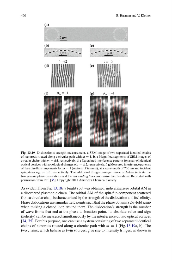
Fig. 13.19 Dislocation’s strength measurement. a SEM image of two separated identical chains
of nanorods rotated along a circular path with m = 1. b, c Magnified segments of SEM images of
circular chains with m = ±1, respectively. d, e Calculated interference patterns for a pair of identical
optical vortices with topological charges of l = ±2, respectively. f, g Measured interference patterns
of the spin-flip components for m = 1 (regions of interest), at a wavelength of 730 nm and incident
spin states λ in = ±1, respectively. The additional fringes emerge above or below indicate the
two generic phase dislocations and the red guiding lines emphasize their locations. Reprinted with
permission from Ref. [35]. Copyright 2011 American Chemical Society
As evident from Fig. 13.18c a bright spot was obtained, indicating zero orbital AM in
a disordered plasmonic chain. The orbital AM of the spin-flip component scattered
from a circular chain is characterized by the strength of the dislocation and its helicity.
Phase dislocations are singular field points such that the phase obtains a 2α -fold jump
when making a closed loop around them. The dislocation’s strength is the number
of wave-fronts that end at the phase dislocation point. Its absolute value and sign
(helicity) can be measured simultaneously by the interference of two optical vortices
[74, 75]. For this purpose, one can use a system consisting of two separated identical
chains of nanorods rotated along a circular path with m = 1 (Fig. 13.19a, b). The
two chains, which behave as twin sources, give rise to intensity fringes, as shown in
E. Hasman and V. Kleiner
m
μ
5
2
−
=
l
2
+
=
l
1
−
=
in
σ
1
+
=
in
σ
m
μ
1
m
μ
1
(a)
(b)
(c)
(d)
(e)
(f)
(g)
Fig. 13.19 Dislocation’s strength measurement. a SEM image of two separated identical chains
of nanorods rotated along a circular path with m = 1. b, c Magnified segments of SEM images of
circular chains with m = ±1, respectively. d, e Calculated interference patterns for a pair of identical
optical vortices with topological charges of l = ±2, respectively. f, g Measured interference patterns
of the spin-flip components for m = 1 (regions of interest), at a wavelength of 730 nm and incident
spin states λ in = ±1, respectively. The additional fringes emerge above or below indicate the
two generic phase dislocations and the red guiding lines emphasize their locations. Reprinted with
permission from Ref. [35]. Copyright 2011 American Chemical Society
As evident from Fig. 13.18c a bright spot was obtained, indicating zero orbital AM in
a disordered plasmonic chain. The orbital AM of the spin-flip component scattered
from a circular chain is characterized by the strength of the dislocation and its helicity.
Phase dislocations are singular field points such that the phase obtains a 2α -fold jump
when making a closed loop around them. The dislocation’s strength is the number
of wave-fronts that end at the phase dislocation point. Its absolute value and sign
(helicity) can be measured simultaneously by the interference of two optical vortices
[74, 75]. For this purpose, one can use a system consisting of two separated identical
chains of nanorods rotated along a circular path with m = 1 (Fig. 13.19a, b). The
two chains, which behave as twin sources, give rise to intensity fringes, as shown in