

13 Spinoptics in Plasmonics
467
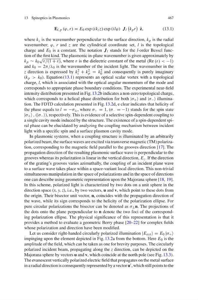
E l, p (π, r ) = E 0 exp (ik z z) exp (ilπ) J l
k p r
ˆ
z,
(13.1)
where k z is the wavenumber perpendicular to the surface direction, k p is the radial
wavenumber; π, r and z are the cylindrical coordinate set, l is the topological
charge and E 0 is a constant. The notation J l stands for the l-order Bessel function of the first kind. The plasmonic in-plane wavenumber is given approximately by
k p ∼ k 0
∝
ω/(1 + ω), where ω is the dielectric constant of the metal (Re (ω) < −1)
and k 0 = 2α/ε 0 is the wavenumber of the incident light. The wavenumber in the
z direction is expressed by k 2
z + k 2
p = k 2
0 and consequently is purely imaginary
(k p > k 0 ). Equation (13.1) represents an optical scalar vortex with a topological
charge, l, which is associated with the optical angular momentum of the mode and
corresponds to appropriate phase boundary conditions. The experimental near-field
intensity distribution presented in Fig. 13.2b indicates a non-zero topological charge,
which corresponds to a helical phase distribution for both |λ + ≈ and |λ − ≈ illumination. The FDTD calculation presented in Fig. 13.2d, e clear indicates that helicity of
the phase equals to l = −λ ± , where λ + = 1, (λ − = −1) stands for the spin state
|λ + ≈ , (|λ − ≈), respectively. This is evidence of a selective spin-dependent coupling to
a single cavity mode induced by the structure. The existence of a spin-dependent spiral phase can be elucidated by analyzing the coupling mechanism between incident
light with a specific spin and a surface plasmon cavity mode.
In plasmonic systems, when a coupling structure is illuminated by an arbitrarily
polarized beam, the surface waves are excited via transverse magnetic (TM) polarization, corresponding to the magnetic field parallel to the grooves direction [17]. The
propagation direction of the resulting plasmonic surface wave is perpendicular to the
grooves whereas its polarization is linear in the vertical direction, E z . If the direction
of the grating’s grooves varies azimuthally, the coupling of an incident plane wave
to a surface wave takes place within a space-variant local direction. This non-trivial
simultaneous manipulation in the space of polarizations and in the space of directions
one can describe using geometric representation upon the Majorana sphere [18, 19].
In this scheme, polarized light is characterized by two dots on a unit sphere in the
direction space (x, y, z), i.e., by two vectors, u and v, which point to these dots from
the origin. Their bisector unit vector, n, coincides with the propagation direction of
the wave, while its sign corresponds to the helicity of the polarization ellipse. For
pure circular polarizations the bisector can be denoted as λ ± n. The projections of
the dots onto the plane perpendicular to n denote the two foci of the corresponding polarization ellipse. The physical significance of this representation is that it
provides a method to evaluate a geometric Berry phase [20–22] for complex fields
whose polarization and direction have been modified.
Let us consider right-handed circularly polarized illumination |E ext ≈ = E 0 |λ + ≈
impinging upon the element depicted in Fig. 13.2a from the bottom. Here E 0 is the
amplitude of the field, which can be taken as one for brevity purposes. The circularly
polarized incident beam, propagating along the z direction, can be depicted on the
Majorana sphere by vectors u and v, which coincide at the north pole (see Fig. 13.3).
The evanescent vertically polarized electric field that propagates on the metal surface
in a radial direction is consequently represented by a vector u , which still points to the
467
E l, p (π, r ) = E 0 exp (ik z z) exp (ilπ) J l
k p r
ˆ
z,
(13.1)
where k z is the wavenumber perpendicular to the surface direction, k p is the radial
wavenumber; π, r and z are the cylindrical coordinate set, l is the topological
charge and E 0 is a constant. The notation J l stands for the l-order Bessel function of the first kind. The plasmonic in-plane wavenumber is given approximately by
k p ∼ k 0
∝
ω/(1 + ω), where ω is the dielectric constant of the metal (Re (ω) < −1)
and k 0 = 2α/ε 0 is the wavenumber of the incident light. The wavenumber in the
z direction is expressed by k 2
z + k 2
p = k 2
0 and consequently is purely imaginary
(k p > k 0 ). Equation (13.1) represents an optical scalar vortex with a topological
charge, l, which is associated with the optical angular momentum of the mode and
corresponds to appropriate phase boundary conditions. The experimental near-field
intensity distribution presented in Fig. 13.2b indicates a non-zero topological charge,
which corresponds to a helical phase distribution for both |λ + ≈ and |λ − ≈ illumination. The FDTD calculation presented in Fig. 13.2d, e clear indicates that helicity of
the phase equals to l = −λ ± , where λ + = 1, (λ − = −1) stands for the spin state
|λ + ≈ , (|λ − ≈), respectively. This is evidence of a selective spin-dependent coupling to
a single cavity mode induced by the structure. The existence of a spin-dependent spiral phase can be elucidated by analyzing the coupling mechanism between incident
light with a specific spin and a surface plasmon cavity mode.
In plasmonic systems, when a coupling structure is illuminated by an arbitrarily
polarized beam, the surface waves are excited via transverse magnetic (TM) polarization, corresponding to the magnetic field parallel to the grooves direction [17]. The
propagation direction of the resulting plasmonic surface wave is perpendicular to the
grooves whereas its polarization is linear in the vertical direction, E z . If the direction
of the grating’s grooves varies azimuthally, the coupling of an incident plane wave
to a surface wave takes place within a space-variant local direction. This non-trivial
simultaneous manipulation in the space of polarizations and in the space of directions
one can describe using geometric representation upon the Majorana sphere [18, 19].
In this scheme, polarized light is characterized by two dots on a unit sphere in the
direction space (x, y, z), i.e., by two vectors, u and v, which point to these dots from
the origin. Their bisector unit vector, n, coincides with the propagation direction of
the wave, while its sign corresponds to the helicity of the polarization ellipse. For
pure circular polarizations the bisector can be denoted as λ ± n. The projections of
the dots onto the plane perpendicular to n denote the two foci of the corresponding polarization ellipse. The physical significance of this representation is that it
provides a method to evaluate a geometric Berry phase [20–22] for complex fields
whose polarization and direction have been modified.
Let us consider right-handed circularly polarized illumination |E ext ≈ = E 0 |λ + ≈
impinging upon the element depicted in Fig. 13.2a from the bottom. Here E 0 is the
amplitude of the field, which can be taken as one for brevity purposes. The circularly
polarized incident beam, propagating along the z direction, can be depicted on the
Majorana sphere by vectors u and v, which coincide at the north pole (see Fig. 13.3).
The evanescent vertically polarized electric field that propagates on the metal surface
in a radial direction is consequently represented by a vector u , which still points to the