

12 Plasmonics with a Twist: Taming Optical Tornadoes on the Nanoscale
455
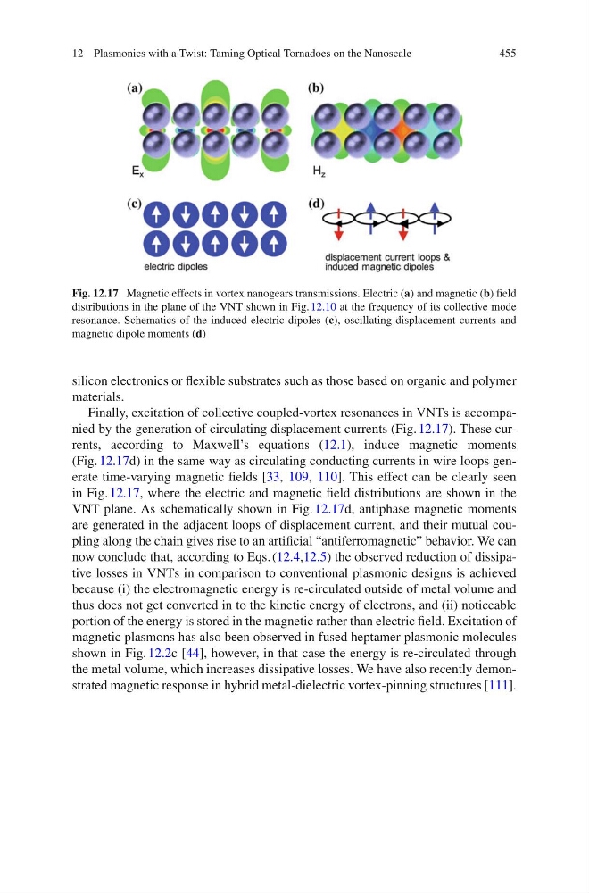
Fig. 12.17 Magnetic effects in vortex nanogears transmissions. Electric (a) and magnetic (b) field
distributions in the plane of the VNT shown in Fig. 12.10 at the frequency of its collective mode
resonance. Schematics of the induced electric dipoles (c), oscillating displacement currents and
magnetic dipole moments (d)
silicon electronics or flexible substrates such as those based on organic and polymer
materials.
Finally, excitation of collective coupled-vortex resonances in VNTs is accompanied by the generation of circulating displacement currents (Fig. 12.17). These currents, according to Maxwell’s equations (12.1), induce magnetic moments
(Fig. 12.17d) in the same way as circulating conducting currents in wire loops generate time-varying magnetic fields [33, 109, 110]. This effect can be clearly seen
in Fig. 12.17, where the electric and magnetic field distributions are shown in the
VNT plane. As schematically shown in Fig. 12.17d, antiphase magnetic moments
are generated in the adjacent loops of displacement current, and their mutual coupling along the chain gives rise to an artificial “antiferromagnetic” behavior. We can
now conclude that, according to Eqs. (12.4,12.5) the observed reduction of dissipative losses in VNTs in comparison to conventional plasmonic designs is achieved
because (i) the electromagnetic energy is re-circulated outside of metal volume and
thus does not get converted in to the kinetic energy of electrons, and (ii) noticeable
portion of the energy is stored in the magnetic rather than electric field. Excitation of
magnetic plasmons has also been observed in fused heptamer plasmonic molecules
shown in Fig. 12.2c [44], however, in that case the energy is re-circulated through
the metal volume, which increases dissipative losses. We have also recently demonstrated magnetic response in hybrid metal-dielectric vortex-pinning structures [111].
455
Fig. 12.17 Magnetic effects in vortex nanogears transmissions. Electric (a) and magnetic (b) field
distributions in the plane of the VNT shown in Fig. 12.10 at the frequency of its collective mode
resonance. Schematics of the induced electric dipoles (c), oscillating displacement currents and
magnetic dipole moments (d)
silicon electronics or flexible substrates such as those based on organic and polymer
materials.
Finally, excitation of collective coupled-vortex resonances in VNTs is accompanied by the generation of circulating displacement currents (Fig. 12.17). These currents, according to Maxwell’s equations (12.1), induce magnetic moments
(Fig. 12.17d) in the same way as circulating conducting currents in wire loops generate time-varying magnetic fields [33, 109, 110]. This effect can be clearly seen
in Fig. 12.17, where the electric and magnetic field distributions are shown in the
VNT plane. As schematically shown in Fig. 12.17d, antiphase magnetic moments
are generated in the adjacent loops of displacement current, and their mutual coupling along the chain gives rise to an artificial “antiferromagnetic” behavior. We can
now conclude that, according to Eqs. (12.4,12.5) the observed reduction of dissipative losses in VNTs in comparison to conventional plasmonic designs is achieved
because (i) the electromagnetic energy is re-circulated outside of metal volume and
thus does not get converted in to the kinetic energy of electrons, and (ii) noticeable
portion of the energy is stored in the magnetic rather than electric field. Excitation of
magnetic plasmons has also been observed in fused heptamer plasmonic molecules
shown in Fig. 12.2c [44], however, in that case the energy is re-circulated through
the metal volume, which increases dissipative losses. We have also recently demonstrated magnetic response in hybrid metal-dielectric vortex-pinning structures [111].