

8 Controlling Thermal Radiation with Surface Waves
297
Fig. 8.11 Sketch of the phase matching and polarization condition in the case of a coupling between
an incident propagating wave and a surface wave. The wave vector of the surface wave κ sw is not
colinear with the grating vector G. The order +1 is shown. The diffracted wave vector is not
colinear with the surface-wave wave vector. The incident wave is s-polarized: the electric field E s
has a component parallel to κ sw , so that it can excite the surface wave
Conversely, a p-polarized surface wave can be coupled to a s-polarized emitted wave
in the far field.
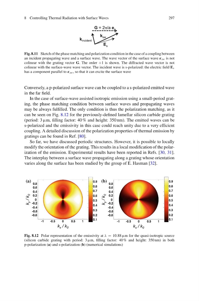
In the case of surface-wave assisted isotropic emission using a small-period grating, the phase matching condition between surface waves and propagating waves
may be always fulfilled. The only condition is thus the polarization matching, as it
can be seen on Fig. 8.12 for the previously-defined lamellar silicon carbide grating
(period: 3 µm, filling factor: 40 % and height: 350 nm). The emitted waves can be
s-polarized and the emissivity in this case could reach unity due to a very efficient
coupling. A detailed discussion of the polarization properties of thermal emission by
gratings can be found in Ref. [80].
So far, we have discussed periodic structures. However, it is possible to locally
modify the orientation of the grating. This results in a local modification of the polarization of the emission. Experimental results have been reported in Refs. [30, 31].
The interplay between a surface wave propagating along a grating whose orientation
varies along the surface has been studied by the group of E. Hasman [32].
(a)
(b)
Fig. 8.12 Polar representation of the emissivity at λ = 10.88 µm for the quasi-isotropic source
(silicon carbide grating with period: 3 µm, filling factor: 40 % and height: 350 nm) in both
p-polarization (a) and s-polarization (b) (numerical simulations)
297
Fig. 8.11 Sketch of the phase matching and polarization condition in the case of a coupling between
an incident propagating wave and a surface wave. The wave vector of the surface wave κ sw is not
colinear with the grating vector G. The order +1 is shown. The diffracted wave vector is not
colinear with the surface-wave wave vector. The incident wave is s-polarized: the electric field E s
has a component parallel to κ sw , so that it can excite the surface wave
Conversely, a p-polarized surface wave can be coupled to a s-polarized emitted wave
in the far field.
In the case of surface-wave assisted isotropic emission using a small-period grating, the phase matching condition between surface waves and propagating waves
may be always fulfilled. The only condition is thus the polarization matching, as it
can be seen on Fig. 8.12 for the previously-defined lamellar silicon carbide grating
(period: 3 µm, filling factor: 40 % and height: 350 nm). The emitted waves can be
s-polarized and the emissivity in this case could reach unity due to a very efficient
coupling. A detailed discussion of the polarization properties of thermal emission by
gratings can be found in Ref. [80].
So far, we have discussed periodic structures. However, it is possible to locally
modify the orientation of the grating. This results in a local modification of the polarization of the emission. Experimental results have been reported in Refs. [30, 31].
The interplay between a surface wave propagating along a grating whose orientation
varies along the surface has been studied by the group of E. Hasman [32].
(a)
(b)
Fig. 8.12 Polar representation of the emissivity at λ = 10.88 µm for the quasi-isotropic source
(silicon carbide grating with period: 3 µm, filling factor: 40 % and height: 350 nm) in both
p-polarization (a) and s-polarization (b) (numerical simulations)