

244
T. Okura
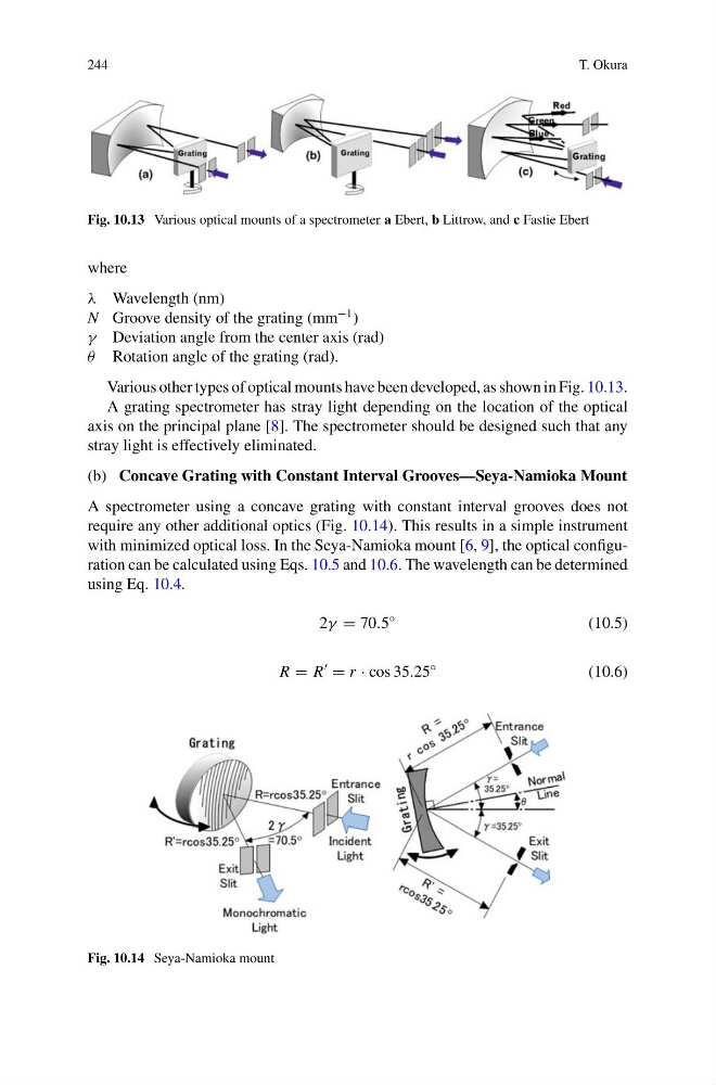
Fig. 10.13 Various optical mounts of a spectrometer a Ebert, b Littrow, and c Fastie Ebert
where
λ Wavelength (nm)
N Groove density of the grating (mm
−1 )
γ Deviation angle from the center axis (rad)
θ Rotation angle of the grating (rad).
Various other types of optical mounts have been developed, as shown in Fig. 10.13.
A grating spectrometer has stray light depending on the location of the optical
axis on the principal plane [8]. The spectrometer should be designed such that any
stray light is effectively eliminated.
(b) Concave Grating with Constant Interval Grooves—Seya-Namioka Mount
A spectrometer using a concave grating with constant interval grooves does not
require any other additional optics (Fig. 10.14). This results in a simple instrument
with minimized optical loss. In the Seya-Namioka mount [6, 9], the optical configuration can be calculated using Eqs. 10.5 and 10.6. The wavelength can be determined
using Eq. 10.4.
2γ = 70.5
◦
(10.5)
R = R
= r · cos 35.25
◦
(10.6)
Fig. 10.14 Seya-Namioka mount
T. Okura
Fig. 10.13 Various optical mounts of a spectrometer a Ebert, b Littrow, and c Fastie Ebert
where
λ Wavelength (nm)
N Groove density of the grating (mm
−1 )
γ Deviation angle from the center axis (rad)
θ Rotation angle of the grating (rad).
Various other types of optical mounts have been developed, as shown in Fig. 10.13.
A grating spectrometer has stray light depending on the location of the optical
axis on the principal plane [8]. The spectrometer should be designed such that any
stray light is effectively eliminated.
(b) Concave Grating with Constant Interval Grooves—Seya-Namioka Mount
A spectrometer using a concave grating with constant interval grooves does not
require any other additional optics (Fig. 10.14). This results in a simple instrument
with minimized optical loss. In the Seya-Namioka mount [6, 9], the optical configuration can be calculated using Eqs. 10.5 and 10.6. The wavelength can be determined
using Eq. 10.4.
2γ = 70.5
◦
(10.5)
R = R
= r · cos 35.25
◦
(10.6)
Fig. 10.14 Seya-Namioka mount