

9 NIR Optics and Measurement Methods
219
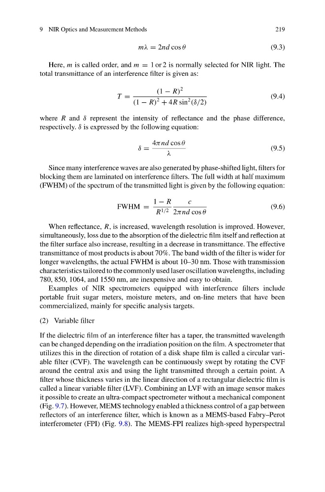
mλ = 2nd cos θ
(9.3)
Here, m is called order, and m = 1 or 2 is normally selected for NIR light. The
total transmittance of an interference filter is given as:
T =
(1 − R)
2
(1 − R)
2
+ 4R sin
2
(δ/2)
(9.4)
where R and δ represent the intensity of reflectance and the phase difference,
respectively. δ is expressed by the following equation:
δ =
4π nd cos θ
λ
(9.5)
Since many interference waves are also generated by phase-shifted light, filters for
blocking them are laminated on interference filters. The full width at half maximum
(FWHM) of the spectrum of the transmitted light is given by the following equation:
FWHM =
1 − R
R 1/2
c
2π nd cos θ
(9.6)
When reflectance, R, is increased, wavelength resolution is improved. However,
simultaneously, loss due to the absorption of the dielectric film itself and reflection at
the filter surface also increase, resulting in a decrease in transmittance. The effective
transmittance of most products is about 70%. The band width of the filter is wider for
longer wavelengths, the actual FWHM is about 10–30 nm. Those with transmission
characteristics tailored to the commonly used laser oscillation wavelengths, including
780, 850, 1064, and 1550 nm, are inexpensive and easy to obtain.
Examples of NIR spectrometers equipped with interference filters include
portable fruit sugar meters, moisture meters, and on-line meters that have been
commercialized, mainly for specific analysis targets.
(2) Variable filter
If the dielectric film of an interference filter has a taper, the transmitted wavelength
can be changed depending on the irradiation position on the film. A spectrometer that
utilizes this in the direction of rotation of a disk shape film is called a circular variable filter (CVF). The wavelength can be continuously swept by rotating the CVF
around the central axis and using the light transmitted through a certain point. A
filter whose thickness varies in the linear direction of a rectangular dielectric film is
called a linear variable filter (LVF). Combining an LVF with an image sensor makes
it possible to create an ultra-compact spectrometer without a mechanical component
(Fig. 9.7). However, MEMS technology enabled a thickness control of a gap between
reflectors of an interference filter, which is known as a MEMS-based Fabry–Perot
interferometer (FPI) (Fig. 9.8). The MEMS-FPI realizes high-speed hyperspectral
219
mλ = 2nd cos θ
(9.3)
Here, m is called order, and m = 1 or 2 is normally selected for NIR light. The
total transmittance of an interference filter is given as:
T =
(1 − R)
2
(1 − R)
2
+ 4R sin
2
(δ/2)
(9.4)
where R and δ represent the intensity of reflectance and the phase difference,
respectively. δ is expressed by the following equation:
δ =
4π nd cos θ
λ
(9.5)
Since many interference waves are also generated by phase-shifted light, filters for
blocking them are laminated on interference filters. The full width at half maximum
(FWHM) of the spectrum of the transmitted light is given by the following equation:
FWHM =
1 − R
R 1/2
c
2π nd cos θ
(9.6)
When reflectance, R, is increased, wavelength resolution is improved. However,
simultaneously, loss due to the absorption of the dielectric film itself and reflection at
the filter surface also increase, resulting in a decrease in transmittance. The effective
transmittance of most products is about 70%. The band width of the filter is wider for
longer wavelengths, the actual FWHM is about 10–30 nm. Those with transmission
characteristics tailored to the commonly used laser oscillation wavelengths, including
780, 850, 1064, and 1550 nm, are inexpensive and easy to obtain.
Examples of NIR spectrometers equipped with interference filters include
portable fruit sugar meters, moisture meters, and on-line meters that have been
commercialized, mainly for specific analysis targets.
(2) Variable filter
If the dielectric film of an interference filter has a taper, the transmitted wavelength
can be changed depending on the irradiation position on the film. A spectrometer that
utilizes this in the direction of rotation of a disk shape film is called a circular variable filter (CVF). The wavelength can be continuously swept by rotating the CVF
around the central axis and using the light transmitted through a certain point. A
filter whose thickness varies in the linear direction of a rectangular dielectric film is
called a linear variable filter (LVF). Combining an LVF with an image sensor makes
it possible to create an ultra-compact spectrometer without a mechanical component
(Fig. 9.7). However, MEMS technology enabled a thickness control of a gap between
reflectors of an interference filter, which is known as a MEMS-based Fabry–Perot
interferometer (FPI) (Fig. 9.8). The MEMS-FPI realizes high-speed hyperspectral