

Fe 3 O 4 þ xLi
þ
þ xe
À
! Li x Fe 3 O 4 :
ð2Þ
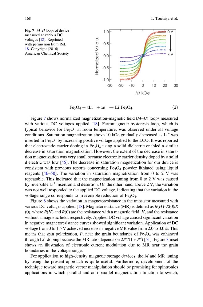
Figure 7 shows normalized magnetization-magnetic field (M–H) loops measured
with various DC voltages applied [18]. Ferromagnetic hysteresis loop, which is
typical behavior for Fe 3 O 4 at room temperature, was observed under all voltage
conditions. Saturation magnetization above 10 kOe gradually decreased as Li
+ was
inserted in Fe 3 O 4 by increasing positive voltage applied to the LCO. It was reported
that electrostatic carrier doping in Fe 3 O 4 using a solid dielectric enabled a similar
decrease in saturation magnetization. However, the extent of the decrease in saturation magnetization was very small because electronic carrier density doped by a solid
dielectric was low [45]. The decrease in saturation magnetization for our device is
consistent with previous reports concerning Fe 3 O 4 powder lithiated using liquid
reagents [46–50]. The variation in saturation magnetization from 0 to 2 V was
repeatable. This indicated that the magnetization tuning from 0 to 2 V was caused
by reversible Li
+ insertion and desertion. On the other hand, above 2 V, the variation
was not well responded to the applied DC voltage, indicating that the variation in the
voltage range corresponds to irreversible reduction of Fe 3 O 4 .
Figure 8 shows the variation in magnetoresistance in the transistor measured with
various DC voltages applied [18]. Magnetoresistance (MR) is defined as R(H)–R(0)/R
(0), where R(H) and R(0) are the resistance with a magnetic field, H, and the resistance
without a magnetic field, respectively. Applied DC voltage caused significant variation
in negative magnetoresistance curves showed significant variation. Application of DC
voltage from 0 to 1.5 V achieved increase in negative MR value from 2.0 to 3.0%. This
means that spin polarization, P, near the grain boundaries of Fe 3 O 4 was enhanced
through Li
+ doping because the MR ratio depends on 2P
2
/(1 + P
2
) [51]. Figure 8 inset
shows an illustration of electronic current modulation due to MR near the grain
boundaries in the voltage range.
For application to high-density magnetic storage devices, the M and MR tuning
by using the present approach is quite useful. Furthermore, development of the
technique toward magnetic vector manipulation should be promising for spintronics
applications in which parallel and anti-parallel magnetization function to switch,
Fig. 7 M–H loops of device
measured at various DC
voltages [18]. Reprinted
with permission from Ref.
18. Copyright (2016)
American Chemical Society
168
T. Tsuchiya et al.
þ
þ xe
À
! Li x Fe 3 O 4 :
ð2Þ
Figure 7 shows normalized magnetization-magnetic field (M–H) loops measured
with various DC voltages applied [18]. Ferromagnetic hysteresis loop, which is
typical behavior for Fe 3 O 4 at room temperature, was observed under all voltage
conditions. Saturation magnetization above 10 kOe gradually decreased as Li
+ was
inserted in Fe 3 O 4 by increasing positive voltage applied to the LCO. It was reported
that electrostatic carrier doping in Fe 3 O 4 using a solid dielectric enabled a similar
decrease in saturation magnetization. However, the extent of the decrease in saturation magnetization was very small because electronic carrier density doped by a solid
dielectric was low [45]. The decrease in saturation magnetization for our device is
consistent with previous reports concerning Fe 3 O 4 powder lithiated using liquid
reagents [46–50]. The variation in saturation magnetization from 0 to 2 V was
repeatable. This indicated that the magnetization tuning from 0 to 2 V was caused
by reversible Li
+ insertion and desertion. On the other hand, above 2 V, the variation
was not well responded to the applied DC voltage, indicating that the variation in the
voltage range corresponds to irreversible reduction of Fe 3 O 4 .
Figure 8 shows the variation in magnetoresistance in the transistor measured with
various DC voltages applied [18]. Magnetoresistance (MR) is defined as R(H)–R(0)/R
(0), where R(H) and R(0) are the resistance with a magnetic field, H, and the resistance
without a magnetic field, respectively. Applied DC voltage caused significant variation
in negative magnetoresistance curves showed significant variation. Application of DC
voltage from 0 to 1.5 V achieved increase in negative MR value from 2.0 to 3.0%. This
means that spin polarization, P, near the grain boundaries of Fe 3 O 4 was enhanced
through Li
+ doping because the MR ratio depends on 2P
2
/(1 + P
2
) [51]. Figure 8 inset
shows an illustration of electronic current modulation due to MR near the grain
boundaries in the voltage range.
For application to high-density magnetic storage devices, the M and MR tuning
by using the present approach is quite useful. Furthermore, development of the
technique toward magnetic vector manipulation should be promising for spintronics
applications in which parallel and anti-parallel magnetization function to switch,
Fig. 7 M–H loops of device
measured at various DC
voltages [18]. Reprinted
with permission from Ref.
18. Copyright (2016)
American Chemical Society
168
T. Tsuchiya et al.