

404
5 Laser Specklometer, Speckle-Optical Diagnostics and Laser …
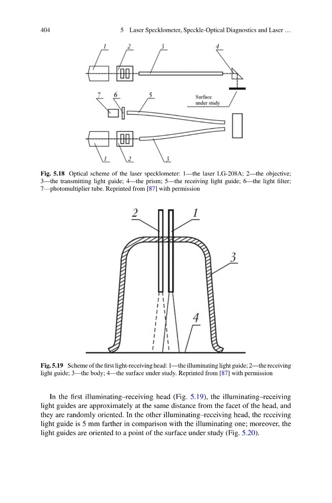
Fig. 5.18 Optical scheme of the laser specklometer: 1—the laser LG-208A; 2—the objective;
3—the transmitting light guide; 4—the prism; 5—the receiving light guide; 6—the light filter;
7—photomultiplier tube. Reprinted from [87] with permission
Fig. 5.19 Scheme of the first light-receiving head: 1—the illuminating light guide; 2—the receiving
light guide; 3—the body; 4—the surface under study. Reprinted from [87] with permission
In the first illuminating–receiving head (Fig. 5.19), the illuminating–receiving
light guides are approximately at the same distance from the facet of the head, and
they are randomly oriented. In the other illuminating–receiving head, the receiving
light guide is 5 mm farther in comparison with the illuminating one; moreover, the
light guides are oriented to a point of the surface under study (Fig. 5.20).
5 Laser Specklometer, Speckle-Optical Diagnostics and Laser …
Fig. 5.18 Optical scheme of the laser specklometer: 1—the laser LG-208A; 2—the objective;
3—the transmitting light guide; 4—the prism; 5—the receiving light guide; 6—the light filter;
7—photomultiplier tube. Reprinted from [87] with permission
Fig. 5.19 Scheme of the first light-receiving head: 1—the illuminating light guide; 2—the receiving
light guide; 3—the body; 4—the surface under study. Reprinted from [87] with permission
In the first illuminating–receiving head (Fig. 5.19), the illuminating–receiving
light guides are approximately at the same distance from the facet of the head, and
they are randomly oriented. In the other illuminating–receiving head, the receiving
light guide is 5 mm farther in comparison with the illuminating one; moreover, the
light guides are oriented to a point of the surface under study (Fig. 5.20).