

5.5 Study on Optimization of Parameters of Measuring Path …
405
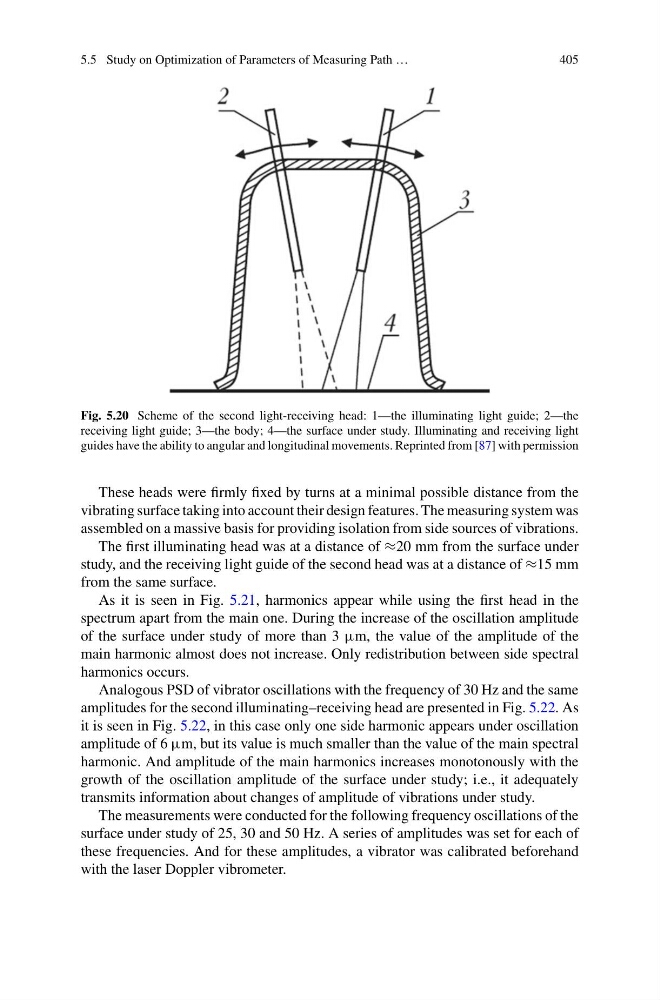
Fig. 5.20 Scheme of the second light-receiving head: 1—the illuminating light guide; 2—the
receiving light guide; 3—the body; 4—the surface under study. Illuminating and receiving light
guides have the ability to angular and longitudinal movements. Reprinted from [87] with permission
These heads were firmly fixed by turns at a minimal possible distance from the
vibrating surface taking into account their design features. The measuring system was
assembled on a massive basis for providing isolation from side sources of vibrations.
The first illuminating head was at a distance of ≈20 mm from the surface under
study, and the receiving light guide of the second head was at a distance of ≈15 mm
from the same surface.
As it is seen in Fig. 5.21, harmonics appear while using the first head in the
spectrum apart from the main one. During the increase of the oscillation amplitude
of the surface under study of more than 3 μm, the value of the amplitude of the
main harmonic almost does not increase. Only redistribution between side spectral
harmonics occurs.
Analogous PSD of vibrator oscillations with the frequency of 30 Hz and the same
amplitudes for the second illuminating–receiving head are presented in Fig. 5.22. As
it is seen in Fig. 5.22, in this case only one side harmonic appears under oscillation
amplitude of 6 μm, but its value is much smaller than the value of the main spectral
harmonic. And amplitude of the main harmonics increases monotonously with the
growth of the oscillation amplitude of the surface under study; i.e., it adequately
transmits information about changes of amplitude of vibrations under study.
The measurements were conducted for the following frequency oscillations of the
surface under study of 25, 30 and 50 Hz. A series of amplitudes was set for each of
these frequencies. And for these amplitudes, a vibrator was calibrated beforehand
with the laser Doppler vibrometer.
405
Fig. 5.20 Scheme of the second light-receiving head: 1—the illuminating light guide; 2—the
receiving light guide; 3—the body; 4—the surface under study. Illuminating and receiving light
guides have the ability to angular and longitudinal movements. Reprinted from [87] with permission
These heads were firmly fixed by turns at a minimal possible distance from the
vibrating surface taking into account their design features. The measuring system was
assembled on a massive basis for providing isolation from side sources of vibrations.
The first illuminating head was at a distance of ≈20 mm from the surface under
study, and the receiving light guide of the second head was at a distance of ≈15 mm
from the same surface.
As it is seen in Fig. 5.21, harmonics appear while using the first head in the
spectrum apart from the main one. During the increase of the oscillation amplitude
of the surface under study of more than 3 μm, the value of the amplitude of the
main harmonic almost does not increase. Only redistribution between side spectral
harmonics occurs.
Analogous PSD of vibrator oscillations with the frequency of 30 Hz and the same
amplitudes for the second illuminating–receiving head are presented in Fig. 5.22. As
it is seen in Fig. 5.22, in this case only one side harmonic appears under oscillation
amplitude of 6 μm, but its value is much smaller than the value of the main spectral
harmonic. And amplitude of the main harmonics increases monotonously with the
growth of the oscillation amplitude of the surface under study; i.e., it adequately
transmits information about changes of amplitude of vibrations under study.
The measurements were conducted for the following frequency oscillations of the
surface under study of 25, 30 and 50 Hz. A series of amplitudes was set for each of
these frequencies. And for these amplitudes, a vibrator was calibrated beforehand
with the laser Doppler vibrometer.