

400
5 Laser Specklometer, Speckle-Optical Diagnostics and Laser …
It is known that the speckle lateral dimension was determined as a = 1.22λL/D
where λ is the wavelength of the laser radiation and D is the illuminated plane. Using
this expression, it is possible to calculate that a ≈ 4 μm. It is seen that the diameter
of the light guide fiber and the speckle diameter almost coincide with each other.
This makes it possible to detect a single signal, to provide maximal sensitivity of the
measurement scheme and to observe the main oscillation harmonic only.
Sinusoidal electric signals are fed with set frequencies onto the USWS using
the generator GZ-ZZ. The frequencies were controlled by the frequency meter.
The dynamic speckle-field scattered by the microinstrument surface was registered
through the receiving light guide (RLG), and the radiation input device (ID) was
registered and transformed into an electric signal using a photomultiplier tube (PMT).
Then through a normalization device (ND), the signal went to the spectrum analyzer
SK4-72 for processing. The amplitude A 1 of the first spectral harmonic of intensity
fluctuation spectrum was registered. The spectrum was scattered by the surface of
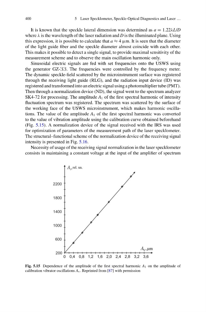
the working face of the USWS microinstrument, which makes harmonic oscillations. The value of the amplitude A 1 of the first spectral harmonic was converted
to the value of vibration amplitude using the calibration curve obtained beforehand
(Fig. 5.15). A normalization device of the signal received with the IRS was used
for optimization of parameters of the measurement path of the laser specklometer.
The structural–functional scheme of the normalization device of the receiving signal
intensity is presented in Fig. 5.16.
Necessity of usage of the receiving signal normalization in the laser specklometer
consists in maintaining a constant voltage at the input of the amplifier of spectrum
Fig. 5.15 Dependence of the amplitude of the first spectral harmonic A 1 on the amplitude of
calibration vibrator oscillations A v . Reprinted from [87] with permission
5 Laser Specklometer, Speckle-Optical Diagnostics and Laser …
It is known that the speckle lateral dimension was determined as a = 1.22λL/D
where λ is the wavelength of the laser radiation and D is the illuminated plane. Using
this expression, it is possible to calculate that a ≈ 4 μm. It is seen that the diameter
of the light guide fiber and the speckle diameter almost coincide with each other.
This makes it possible to detect a single signal, to provide maximal sensitivity of the
measurement scheme and to observe the main oscillation harmonic only.
Sinusoidal electric signals are fed with set frequencies onto the USWS using
the generator GZ-ZZ. The frequencies were controlled by the frequency meter.
The dynamic speckle-field scattered by the microinstrument surface was registered
through the receiving light guide (RLG), and the radiation input device (ID) was
registered and transformed into an electric signal using a photomultiplier tube (PMT).
Then through a normalization device (ND), the signal went to the spectrum analyzer
SK4-72 for processing. The amplitude A 1 of the first spectral harmonic of intensity
fluctuation spectrum was registered. The spectrum was scattered by the surface of
the working face of the USWS microinstrument, which makes harmonic oscillations. The value of the amplitude A 1 of the first spectral harmonic was converted
to the value of vibration amplitude using the calibration curve obtained beforehand
(Fig. 5.15). A normalization device of the signal received with the IRS was used
for optimization of parameters of the measurement path of the laser specklometer.
The structural–functional scheme of the normalization device of the receiving signal
intensity is presented in Fig. 5.16.
Necessity of usage of the receiving signal normalization in the laser specklometer
consists in maintaining a constant voltage at the input of the amplifier of spectrum
Fig. 5.15 Dependence of the amplitude of the first spectral harmonic A 1 on the amplitude of
calibration vibrator oscillations A v . Reprinted from [87] with permission